
What is CNC Machining?
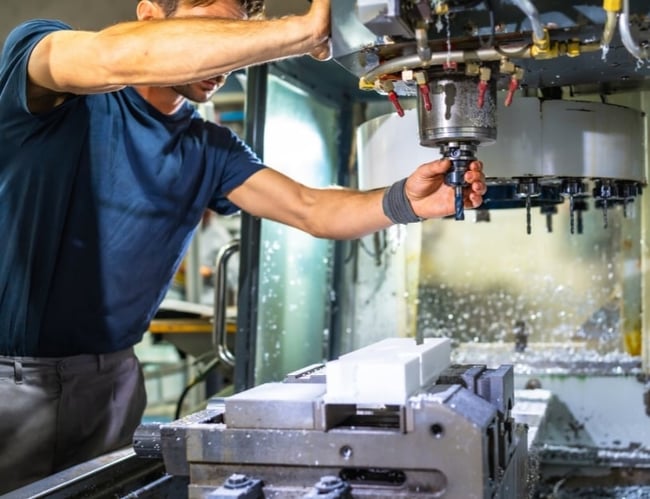
CNC machining is a subtractive manufacturing process where computer-controlled machine tools remove material from a solid workpiece to produce a finished part.
Updated: 8/20/26
What is the CNC machining process?
Whether it falls into a low-volume, prototype run or a high-volume production run, a CNC machined part generally follows the same workflow:
- CAD model and engineering drawing – an engineer provides a 3D CAD model, 2D technical drawing, and any other documentation that can aid in manufacturing
- CAM Programming – a CNC programmer uploads the CAD model into CAM software (e.g., Esprit, GibbsCAM), and defines the necessary tools, toolpaths, speeds, and feeds based on the chosen material and machine
- Setup – a setup machinist confirms offsets, loads toolkits, and verifies the program for production
- Machining – an operator loads the stock material (either into a fixture or barfeeder, depending on the machine and chosen workpiece material), runs the job to achieve desired quantity, and completes any in-process, manual or first article inspections
- Post-machining operations (if necessary) – parts are sent to post-machining operations (e.g., chromate, anodize, chem-film) prior to final assembly or shipment
- Inspection – the finished part is inspected against the technical drawing using either manual metrology equipment (e.g., micrometers, calipers), a coordinate measurement machine (CMM), or profilometer.
What are the types of CNC machines?
There are many types of CNC machines, and the most common include CNC mills, CNC lathes, Swiss-type lathes, and CNC routers.
Other types of CNC machines use thermal and electrical processes to form components, including CNC laser cutters, plasma cutters, and electrical discharge machines (EDM). This article focuses exclusively on CNC mill and CNC lathe machines.
What is CNC milling?
CNC milling is a machining process where the cutting tool in CNC milling rotates and moves around a stationary workpiece to shape a part. Unlike turning, which works only with cylindrical parts, milling can create a wide range of shapes and contours in materials that are challenging or even impossible to machine with other methods.
CNC milling machines are largely categorized into two main types: vertical machining centers (VMCs) and horizontal machining centers (HMCs), and within these categories, they’re further sorted by their axis count (i.e., 3-axis and 5-axis mills).
What is CNC turning?
CNC turning is a machining process where a lathe is used to rotate the metal while a cutting tool moves in a linear motion to remove metal along the diameter, creating a cylindrical shape.
Turning produces rotational, typically axi-symmetric, parts with many features, such as holes, grooves, threads, tapers, various diameter steps, and even contoured surfaces.
What are machining tolerances?
CNC tolerance is the acceptable range for a finished measurement to pass inspection. Because no machined feature can be produced to an exact dimension every time, the tolerance defines how much the measurement may vary.
A machining tolerance is written as a plus or minus band, like ±0.02″, so a 1.000″ feature held to ±0.02″ can measure 0.98″ to 1.02″. Every machined feature carries a tolerance because no cut is ever perfect.
Tight tolerance means that there’s less room for error when manufacturing a part, which typically manifests as increased costs across production.
For reference, here are the tolerances we hold at Hirsh Precision.
| Distance Dimensions |
For features of size and location: +/- 0.005”. Orientation and form dimensions: 0-12" +/- 0.005", Angularity 1/2 degree |
| Precision Tolerances |
Hirsh can hold tight tolerances, including sub +/- 0.001" tolerances, per your drawing specifications and GD&T callouts Anything below ±.001 will require an internal review prior to quoting. |
| Shaft Diameters (lathe parts) |
+/- 0.00016" (+/- 0.004 mm) for metals, PEEK, and ULTEM +/- 0.002" (+/- 0.05 mm) for other plastics |
Types of Tolerances
CNC tolerances typically fall into three categories: standard, tight, and precision.
Standard Tolerances: ±0.005" (±0.127 mm)
This is the default for most CNC shops. If your drawing has no tolerance listed, most shops use ±0.005". It works for clearance holes, mounting surfaces, and general outlines.
Tight Tolerances: (±0.002" (±0.050 mm)
Tight tolerances are used for components that must fit together precisely, such as bearing bores, locating pins, and sliding fits. Achieving them requires additional machining passes and more frequent dimensional checks.
Precision Tolerances: ±0.001" (±0.025 mm)
Precision tolerances are the tightest typically used in standard CNC milling. They require slower feed rates, well-maintained cutting tools, and careful setup. Reserve them for critical mating surfaces, which are common in aerospace and medical components.
What is machining cost?
Machining cost is the combined cost of all the fixed and variable costs associated with an individual machined component.
It’s determined at the quote stage (although strategic machining partners can lower cost over time) by designing a manufacturing process that takes into account part complexity, material, tolerances, inspection requirements, and post-machining operations.
What are the main cost drivers in CNC machining?
Material selection, part complexity, setup/programming, tolerances, cycle time, and post-processing are the main cost drivers in CNC machining.
In general, you can think about machining cost drivers in two categories: fixed and scaled costs.
Fixed costs represent the foundational expenses incurred at the start of a CNC machining project; these costs primarily include setup and programming. Regardless of the quantity of parts ordered, these costs are amortized across the entire production run.
Scaled costs correspond directly to order volume and include material, machining process, tooling, tolerances, and post-processes. If you place a high-volume order, naturally you’ll spend more on these things compared to a low-volume run.
How to design for CNC machining?
CNC machining demands precision and accuracy to create high-quality designs. While CNC machining provides significant design flexibility, it does have some limitations. These are mainly due to the mechanics of the cutting process, particularly tool access and tool geometry.
Tool Access
The cutting tool removes material by approaching the workpiece from above. If a feature cannot be accessed this way, it cannot be CNC machined (with the exception of undercuts). Design parts for CNC machining using tools with the largest diameter and shortest length to simplify production.
Tool Geometry
Most CNC cutting tools, like end mills and drills, are cylindrical and have a limited cutting length. When material is cut away, the tool's shape is mirrored in the part. This means the internal corners of a CNC part will always have a radius, regardless of the tool's size.
To optimize your designs for CNC machining, follow these general DFM principles (get more design tips in our DFM article).
Wall Thickness
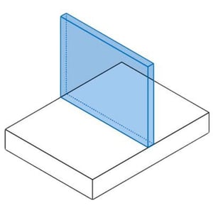
Recommended Thickness: 0.8 mm for metals, 1.5 mm for plastics
Reducing wall thickness makes the material less stiff, leading to more vibrations during machining and less accuracy. Plastics can warp due to stress and soften with heat, so it's best to use thicker walls. Always assess the recommended values individually for each case.
The minimum wall thickness is 0.8 mm for metals and 1.5 mm for plastics. For thinner walls, consider using other cost-effective methods like sheet metal fabrication.
Tolerances
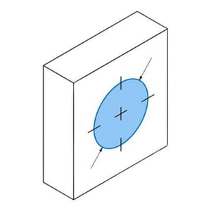
Recommended Tolerance: ± 0.02
Tolerances define the boundaries for an acceptable dimension. The achievable tolerances vary according to the base dimension and the geometry of the part. The values above are reasonable guidelines.
If you don't set specific tolerances, the machine will use its default settings, saving time and money. Only specify tight tolerances when necessary, and keep them consistent throughout your design to reduce machining time.
Threads
Recommended Thread Size: M1 (and lower depending on the situation)
Recommended Thread Length: 3x nominal diameter
Threads are created using taps for internal threads and dies for external threads, capable of cutting down to M2. CNC threading tools are widely used and favored by machinists because they reduce the risk of tap breakage and can cut threads down to M6.
Unnecessarily long threads increase machining costs. The strength of the connection does not increase when the thread length exceeds the size of the diameter by more than 1.5 times. This means that threads longer than 3x the nominal diameter are unnecessary from both a manufacturability standpoint, but also costing one.
- Threads should be no longer than 3 times the hole diameter
- For blind holes, ensure there is an unthreaded section at the bottom that is at least half the diameter of the hole
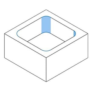
Pockets
Recommended cavity depth: 4x the cavity width
End mill tools have a limited cutting length (typically 3–4 times their diameter). Deep cavities can cause tool hanging, deflection, chip removal problems, and tool breakage. Keep cavity depths to 3-4 times their width to get good results.
For deeper cavities (6x their width), design with variable depths. You can achieve a greater diameter-to-cavity depth ratio (i.e., a maximum depth of 35 cm with a 1-inch diameter end mill); just keep in mind that specialty tooling will be required.
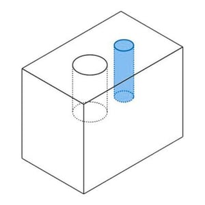
Small Features
Recommended: 2.5 mm (0.1")
Most machine shops can precisely create cavities and holes with tools as small as 2.5 mm (0.1 inches) in diameter. Features smaller than this require micro-machining, which involves specialized tools and expertise due to changes in cutting physics. It is advisable to avoid such features unless absolutely necessary.
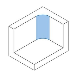
Internal Edges
Recommended Vertical Radius: ⅓ x cavity depth
Recommended Floor Radius: 0.5 mm, 1 mm, or none
Using the recommended internal corner radii ensures the use of the right tool diameter and matches the guidelines for cavity depth.
By slightly increasing the corner radii beyond the recommended value (such as by 1 mm), the tool can cut in a circular path rather than at a 90-degree angle. This approach is preferred as it enhances the surface finish quality. If you need sharp 90-degree internal corners, consider using a T-bone undercut instead of reducing the corner radius.
End mill tools feature a flat or slightly rounded bottom edge. For different floor radii, ball end tools are used. Following the recommended values is a best practice, as machinists prefer them.
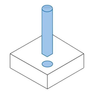
Holes
Recommended Diameter: Standard drill bit (or larger than 1mm)
Recommended Depth: 4x nominal diameter (10x nominal diameter is common)
End mill tools feature a flat or slightly rounded bottom edge. For different floor radii, ball end tools are used. Following the recommended values is a best practice, as machinists prefer them. To machine holes quickly and accurately, use standard drill bits or end mills. This eliminates the need for extra tools to fit non-standard sizes.
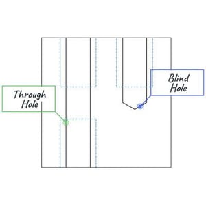
For holes with non-standard diameters, use an end mill tool. Follow the maximum cavity depth guidelines. If a hole is deeper than usual, use specialized drill bits with at least a 3mm diameter. Blind holes drilled have a conical floor at a 135-degree angle, while those machined with an end mill tool have a flat floor.
In CNC machining, there is no specific preference for using through holes or blind holes.
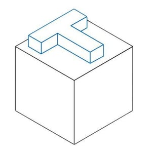
Lettering
Text can be added to the machined part by painting or laser engraving during finishing. If you need the text to be machined, follow these guidelines:
- Opt for engraving rather than embossing to minimize material removal
- Choose 20-point Sans Serif fonts (many CNC machines have pre-programmed fonts like Arial or Verdana) to engrave or letter your parts