Overview
Geometric dimensioning and tolerancing (GD&T) is a system that communicates design intent and defines the desired dimensions and tolerances of manufactured parts.
It uses a symbolic language on engineering drawings and 3D models to describe geometry and its variations. This ensures parts and assemblies are made consistently and accurately.
GD&T follows the ASME Y14.5-2018 standard, which details how to control part geometry in technical drawings.
Benefits of using GD&T:
- Standardized language that conveys design intent
- Precise communication between engineers and manufacturers
- Method for calculating the worst-case mating limits
- Repeatable production and inspection processes
- Assembly is assured from qualified production parts
Essentially, GD&T is a set of rules and symbols that create a language for defining geometry and its variations. You don't need to memorize every symbol, but it's important to understand the basic framework of how it works.
In this guide, we'll briefly discuss technical drawings and review feature control frames, DFRs, datums, and GD&T symbols.
Technical Drawings
A technical drawing, also known as an engineering drawing, is a detailed and precise representation of an object or system that is used in the field of machining and Geometric Dimensioning and Tolerancing (GD&T). These drawings serve as a universal language for engineers and machinists, providing all the necessary information to manufacture and inspect parts accurately.
A technical drawing is a graphical representation that conveys the geometry, dimensions, and tolerances of a part or assembly. It includes detailed views, sections, and notes that describe the specifications and requirements for manufacturing.
The primary purpose of a technical drawing is to communicate the design intent clearly and unambiguously. It ensures that everyone involved in the manufacturing process, from designers to machinists, understands the exact requirements and can produce the part to the specified standards.
A typical technical drawing includes several key components:
- Views – different perspectives of the part, such as front, top, side, and isometric views
- Dimensions – measurements that specify the size and location of features on the part
- Tolerances – allowable variations in dimensions to ensure proper fit and function
- Notes – additional information, such as material specifications, surface finish requirements, and assembly instructions
- Symbols – standardized symbols used in GD&T to indicate geometric characteristics and controls
Technical drawings are crucial in the manufacturing process because they provide a clear and standardized way to convey complex information. They help ensure that parts are made correctly, reduce the risk of errors, and facilitate communication between different departments and stakeholders.

Feature Control Frame
A feature control frame (FCF) is a critical element in GD&T used in machining and technical drawings. It provides a standardized way to specify the geometric characteristics and tolerances of a part feature, ensuring that the part meets the required design specifications.
A feature control frame (FCF) is a rectangular box that contains the geometric characteristic symbol, tolerance value, and any additional modifiers or datum references. It is used to define the allowable variation in the geometry of a part feature, such as its form, orientation, location, or profile.
The primary purpose of an FCF is to communicate the specific geometric requirements for a part feature clearly and unambiguously. It ensures that everyone involved in the manufacturing and inspection processes understands the exact tolerances and can produce and verify the part to the specified standards.
A typical feature control frame includes the following components:
- Geometric characteristic symbol: indicates the type of geometric control, such as flatness, perpendicularity, or position
- Tolerance value: specifies the allowable variation in the feature's geometry
- Modifiers: additional symbols that provide further information about the tolerance, such as maximum material condition (MMC) or least material condition (LMC)
- Datum references: identifies the datums (reference points or planes) used to establish the tolerance zone
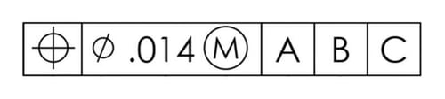
Let’s break down an FCF in more detail.

The first section of an FCF includes a geometric characteristic symbol. Each frame can hold only one symbol. If a feature has two requirements, use either two separate frames or a composite tolerance. The symbol indicates the type of control applied to the feature.
The second part of an FCF shows the complete tolerance for the feature. This tolerance is always a total value, not a plus/minus range.
After the feature tolerance in the FCF, you might see a material condition modifier like Max Material Condition (MMC) or Least Material Condition (LMC) for features of size, such as holes.
Engineers use MMC, LMC and RFS to specify that a tolerance is linked to a feature’s size.
Maximum Material Condition (MMC) - the condition where a feature holds the most material possible within specified size limits, such as the largest pin or the smallest hole
Least Material Condition (LMC) - the condition where the feature contains the least material within the stated limits of size. (ex: smallest pin and/or largest hole)
Regardless of Feature Size (RFS) – the default setting of a feature control frame means the geometric control applies no matter the size or shape variations of other part features
These material condition modifiers are placed in a feature control frame after the feature tolerance. Using MMC and LMC modifiers allows for extra geometric tolerance, known as "bonus" tolerance, when features move away from the specified condition.
If no modifier is specified, the default is RFS (Regardless of Feature Size), though it's not shown in the frame. For non-size features, like plane surfaces, these modifiers aren't used.
The remaining sections of the feature control frame will include datum feature references if needed. For instance, if a form tolerance like flatness or straightness is specified, no datum reference is used. Conversely, if a location tolerance, such as position, is specified, datum references are typically included.
The order of datum references is based on their importance, not the alphabet. They are read from left to right as primary, secondary, and tertiary, and typically read Datum A as the primary, followed by B and C. More on this in the next section.
Datum Reference Frame
Datum reference frames and datum features help us answer the foundational question – what do we measure against? How do we use relative and absolute measurements to check a part when its surfaces and features aren't perfect?
To ensure all features and their dimensional tolerances are consistently checked, we use the datum reference frame.
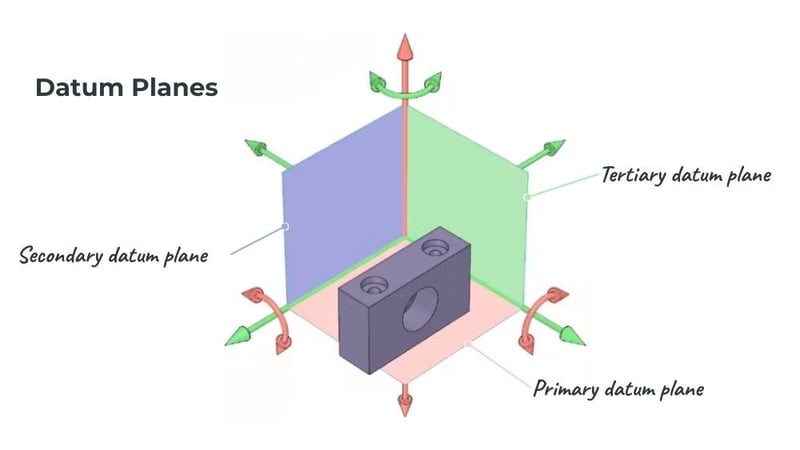
A datum reference frame (DRF) is three mutually perpendicular intersecting datum planes. The datum reference frame establishes a shared set of orthogonal planes that is leveraged by all subsequent feature controls and tolerances that you specify.
.jpg?width=800&height=450&name=Diagram%20of%20a%20datum%20reference%20frame%20(DRF).jpg)
In GD&T, the DRF defines the coordinate system in which all other dimensions and tolerances are specified. This allows for the use of geometric tolerances, which are tolerances that specify the allowable deviation of a feature from its ideal shape or orientation, rather than just specifying the allowable deviation of a single linear dimension.
Without a properly constructed DRF, your feature controls may not communicate your design intent.
A DRF is built along three datum planes: the primary, secondary, and tertiary. These planes constrain the degrees of freedom in translation (x, y, and z axes) and rotation (u, v, and w rotations).
The Role of Datums
A datum is a theoretically exact point, axis, line, plane, or combination thereof derived from the theoretical datum feature simulator.
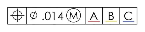
Within the context of a feature control frame, there are three datums (A, B, and C) that are aligned with the primary, secondary, and tertiary planes and read from left to right.
Datums are determined by selecting specific features on the part. While these features are based on datum planes, they do not always have to be planes themselves.
Datum features are based on points of contact and are ordered according to the degrees of freedom that physically constrain the part (critical for inspection purposes). This is commonly referred to as the 3-2-1 rule, which defines the number of points of contact required to establish the primary, secondary, and tertiary datum planes. We’ll cover datum features more thoroughly in the next section.
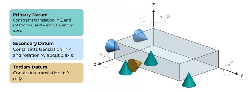
Datum A
This is the primary datum, as it corresponds to the primary plane. Datum A is the first to make contact and requires at least three points of contact. In the example below, Datum A constrains the Z axis, or translation, and the U and V rotations along the X and Y axes, respectively.
Datum B
Think of this as the secondary datum, which corresponds to the secondary plane. Datum B requires two points of contact and constrains the Y axis and the W rotation along the Z axis.
Datum C
This functions as the tertiary datum and corresponds to the tertiary plane. Datum C is the least important, although not irrelevant, of the datums and has only one point of contact. In the example below, it only constrains the X axis.
Here's an example of all 3 datums represented on a single part.
Datum Features
There are countless ways to define a DFR, but all of them depend on choosing datum features.
Datum features are specific part features, such as faces, edges, and vertices, that are identified with either a datum feature symbol or a datum target symbol. These features are associated with real parts and are not theoretical.
Understanding the difference between Datum Features and Datums is crucial. Although they are connected, they are distinct, and this distinction is crucial when setting up a Datum Reference Frame.
A datum is a perfect theoretical plane, axis, or point, while a datum feature is the actual, imperfect surface of the part that defines the datum.
This table lists the different datum features, how they constrain degrees of freedom, and how a datum feature callout is shown on a technical drawing.

GD&T Symbols
Geometric tolerances are set on these features using feature control frames, which use symbols to show the allowed tolerance. These characteristics and their symbols fall into four main categories (or characteristics of features): form, orientation, location, and runout.

Form Tolerances
Control the "shape" of features and are often used as a refinement of size, which means they do not require a datum reference.


Orientation Tolerances
Control the "tilt" of features, link to basic angle dimensions, and refine location. Because orientation GD&T is relative, these feature control frames always reference a datum. When applied to surfaces, orientation tolerances manage form.


Location Tolerances
Control the location and are linked to basic linear dimensions. Location GD&T can position a feature or its size based on the feature itself or a set of derived median points. These characteristics are highly versatile and powerful, allowing control over size, form, and orientation within a single feature control frame.


Runout Tolerances
Control the functional and rotational accuracy of a part feature, usually cylindrical or rotational parts, by limiting how much a surface or feature can deviate as it spins around a datum axis.