What is CNC Turning?
CNC turning is a subtractive manufacturing process used to produce rotational, cylindrical, and concentric features from a workpiece. The machine rotates the part while a computer-controlled cutting tool removes material to create the specified geometry.
Updated: 9/8/26
How does CNC turning work?
CNC turning is commonly used for shafts, pins, bushings, fittings, valve components, threaded bodies, housings, surgical instruments, and other parts whose primary features are symmetric about a centerline.
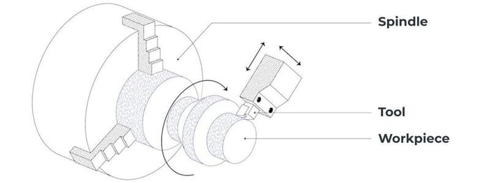
In CNC turning operations, raw material—typically bar stock, tube, or a preformed blank—is held in a chuck, collet, or other workholding device and rotated by the spindle. A stationary cutting tool moves relative to the rotating workpiece along programmed axes, usually:
- X-axis: Controls the tool’s radial position, which establishes diameters.
- Z-axis: Controls movement along the part centerline, which establishes lengths and axial features.
The CNC program defines the cutting path, spindle speed, feed rate, tool selection, coolant use, and other machining parameters. Modern CNC lathes may also include a programmable tailstock, subspindle, live tooling, automatic bar feeder, parts catcher, in-process probing, and automated part handling.
Common turning operations include:
- Facing: Producing a flat surface perpendicular to the part centerline.
- OD turning: Reducing or profiling an outside diameter.
- ID boring: Enlarging or finishing an internal diameter.
- Drilling and reaming: Producing or sizing axial holes.
- Grooving and undercutting: Creating reliefs, seal grooves, retaining-ring grooves, or geometric transitions.
- Threading: Cutting external or internal threads.
- Parting-off: Separating the finished part from bar stock.
- Knurling: Forming a grip texture or mechanical retention feature.
- Taper and contour turning: Producing angled, radiused, or otherwise profiled rotational surfaces.
For critical components, the process plan should account for material condition, stock allowance, clamping method, tool access, heat generation, chip control, and inspection strategy. A part can be dimensionally correct when unclamped yet shift during machining because of thin walls, residual stress, unsupported length, or excessive cutting forces. Designing for stable workholding and maintaining adequate section stiffness are therefore central to achieving repeatable results.
Typical process flow
A typical production route may include:
- Load bar stock or a blank into the machine.
- Establish the work coordinate system and verify tool offsets.
- Rough-machine major diameters and profiles.
- Finish-machine critical diameters, faces, bores, grooves, and threads.
- Transfer the part to a subspindle or secondary operation if back-side features require machining.
- Deburr, clean, and inspect the part according to the control plan.
- Apply any required finishing process, such as passivation, anodizing, electropolishing, heat treatment, coating, or marking.
What are the types of CNC turning machines?
In turning operations, the term “CNC lathe” covers several machine configurations. The right platform depends on the part geometry, required features, annual volume, tolerance requirements, material, and secondary-operation strategy.
| Machine type | Primary capability | Best suited for |
|---|---|---|
| CNC lathe / 2-axis lathe | X- and Z-axis turning with a fixed or indexing turret | Simple rotational parts, such as pins, bushings, sleeves, and basic threaded components |
| Toolroom CNC lathe | Flexible setup, manual intervention capability, low-volume production | Prototypes, first articles, fixtures, engineering changes, and low-volume precision parts |
| CNC turning center | Turning plus automated turret functions, often with a tailstock, bar feeder, or parts catcher | Production components requiring repeatability and a broader range of turning operations |
| Live-tool lathe | Rotating driven tools enable off-center drilling, milling, cross-holes, flats, and slots | Parts requiring limited milled features without moving to a separate milling machine |
| Y-axis turning center | Adds Y-axis motion for more capable off-center milling and drilling | Complex turned parts with flats, pockets, bolt patterns, keyways, or non-central features |
| Subspindle / dual-spindle lathe | Transfers the workpiece between main and secondary spindles | Complete machining of both ends of a part in one setup or one automated cycle |
| Swiss-type lathe | Guide bushing supports small-diameter bar close to the cutting zone | Long, slender, small-diameter precision parts, especially pins, bone screws, fasteners, and miniature fittings |
| Vertical turning center | Holds the workpiece on a vertical rotary table | Large, heavy, or awkwardly shaped rotational components |
Turning centers with live tooling
A turning center with live tooling is often the most economical choice for parts that are mostly rotational but contain a limited number of non-rotational features. For example, a stainless-steel fitting may require turned diameters, internal threads, a cross-drilled port, and wrench flats. Producing all of these features in one machine can reduce setups, handling, fixture variation, and cumulative positional error. However, live tooling does not make every part a good turning candidate. Deep pockets, broad planar surfaces, complex 3D contours, and extensive prismatic geometry are generally more appropriate for a machining center.
Swiss-type turning
Swiss-type lathes are particularly effective for high-precision, small-diameter parts with high length-to-diameter ratios. Unlike a conventional lathe, the bar stock can move axially through a guide bushing while tools cut close to that support point. This reduces deflection and helps maintain dimensional stability on slender features. These machines are widely used for implantable-device components, surgical fasteners, miniature aerospace connectors, precision pins, and microfluidic or analytical-instrument components. They can also combine turning, cross-drilling, milling, threading, and back-working in a single automated cycle.
When to choose CNC turning?
Choose CNC turning when the part’s defining geometry is rotational about a single centerline. Turning is generally the preferred process when most critical features are diameters, bores, shoulders, grooves, tapers, threads, and axial faces.
CNC turning is especially well suited when the design requires:
- Multiple concentric diameters or bores
- Tight runout, coaxiality, or concentricity relationships
- Cylindrical sealing surfaces or precision bearing journals
- Internal or external threads
- Long, slender geometries that would be difficult to fixture on a mill
- High-volume production from bar stock
- Complete machining from one or two spindle setups
- Efficient removal of material from round stock
- Fine surface finishes on cylindrical or axial features
For rotational parts, turning often provides better material utilization and shorter cycle times than milling the same geometry from a block. It also typically reduces the number of fixtures and setups needed to establish concentric relationships.
A useful design rule is: if the part can be described primarily by a cross-sectional profile revolved around a centerline, evaluate CNC turning first.
Lathes vs. Mills
The shape of your part is the most important determining factor in choosing a CNC machining process. If the part is prismatic (i.e., looks like a box), you should use a mill. If the part is round or cylindrical, you should use a lathe.
In addition to part shape, part features also indicate which machining process you should use.
|
Part Feature |
Best Process |
|
Flat surfaces, pockets |
Milling |
|
Round OD, bores |
Turning |
|
External threads |
Turning |
|
Slots, keyways |
Milling |
Mill-Turn Machines
Many parts, like turbine blades and impellers, are complex enough to require milling and turning operations. One option is to complete the first operation on one machine and then move it to the next; however, this could result in alignment issues.
Your other option is to combine both operations into one, which is achievable with a mill-turn machine.
A mill-turn machine combines a mill and a lathe into one machine and one operation. The machine’s spindle spins the part for turning operations, but it can be locked and milled with live tooling.
Choose a mill-turn machine when:
- You want to avoid concentricity and alignment issues by moving your part between machines
- The part’s features require milling and turning operations (e.g., your part is cylindrical and has slots, keyways, cross holes, or other types of flflat features)
While machining hours are more expensive on a mill-turn machine than a mill or a lathe, the reduced setups and improved accuracy are worth the cost for the right part.
Frequently asked questions about CNC turning
What is the difference between CNC turning and milling?
5-axis machining reduces the number of setups by using its rotary axes to reorient the tool or workpiece while the part remains clamped. This lets the machine reach multiple faces under CNC control without removing, flipping, or re-clamping the part.
What is a turn-mill center?
A turn-mill center, also called a mill-turn or multitasking CNC machine, combines turning, milling, drilling, and tapping in one CNC-controlled setup. It is designed for mostly cylindrical parts that also need non-round or off-axis features.
What advantages does a Y-axis provide on a CNC latahe?
A Y-axis adds a third linear direction to a CNC lathe, perpendicular to the normal X–Z turning plane. It lets the turret move off the spindle centerline, enabling more complex mill-turn features without removing and re-fixturing the part.
What is live tooling?
Live tooling is a powered toolholder on a CNC lathe or turning center. It allows selected turret stations to rotate drills, end mills, taps, saws, and similar cutters under CNC control instead of using only stationary turning tools.
Can live tooling fully replace a vertical machining center?
No. Live tooling cannot fully replace a vertical machining center (VMC) in most shops. It can perform many secondary milling, drilling, and tapping operations on turned parts, but it is best treated as an extension of a CNC lathe, not a replacement for a purpose-built mill.
When should you choose a mill-turn over a lathe with live tooling?
Choose a mill-turn when a mostly cylindrical part also needs substantial milling, difficult tool access, angled features, or complete front-and-back machining. These requirements may exceed the rigidity, tool capacity, or overall capability of a lathe with live tooling.