Understanding Functional Intent
Functional intent turns GD&T into true engineering by focusing on the whole system—how parts interact, how variation stacks up, and how performance is achieved.
GD&T is often described as a standardized symbolic language. While this characterization is technically accurate, it is incomplete. GD&T is not simply a notation system—it is a functional communication framework intended to translate design requirements into manufacturable and inspectable outcomes. At the center of this framework lies a critical concept: functional intent.
Functional intent defines why a feature exists, how it must perform, and what variation can be tolerated without compromising the performance of the final assembly.

When properly understood and applied, functional intent transforms a drawing from a static geometric description into a dynamic engineering specification that ensures parts function correctly in service.
Defining Functional Intent
Functional intent refers to the design-driven requirements that ensure a component fulfills its intended role in service. These requirements are derived from:
- Assembly relationships
- Motion or kinematic constraints
- Load paths and stress conditions
- Sealing, alignment, or clearance needs
- Regulatory or safety considerations
Traditional coordinate dimensioning often fails to capture this relationship. While it may define size and location, it does not necessarily describe how those attributes affect performance in the assembled state. GD&T addresses this shortcoming by providing a system that communicates both allowable variation and its functional significance.
In essence, functional intent answers three core questions:
- What must this feature do?
- How does it interact with mating components?
- What variation can be tolerated without compromising performance?
GD&T serves as the communication framework to encode these answers into the engineering definition.
Functional Intent as the Foundation of GD&T
Every GD&T decision should trace back to functional intent, which is conveyed through datum selection, tolerance type selection, and tolerance magnitude.
Datum Selection
The datum reference frame (DRF) is the backbone of any GD&T scheme. It defines how a part is oriented and constrained during manufacturing and inspection. Critically, the DRF should replicate how the part is located within the assembly.
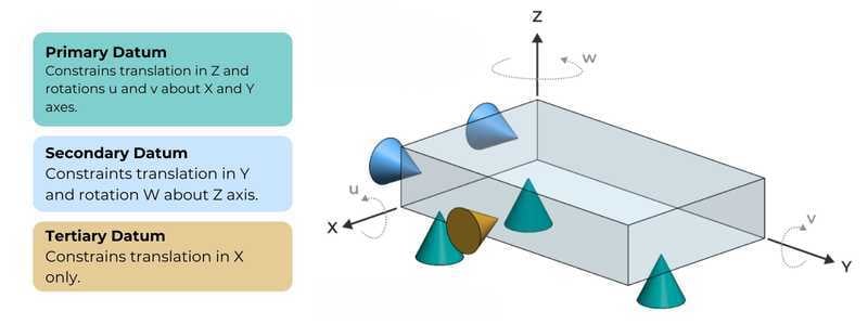
ASME Y14.5 emphasizes that datum selection should be based on the function of the part relative to its mating components. A poorly chosen datum system can misrepresent real-world constraints and lead to parts that pass inspection but fail in service.
Consider a machined bracket mounted to a base structure. The mounting surface should typically serve as the primary datum because it establishes stability and load transfer. Secondary and tertiary datums should reflect how the part is laterally and rotationally constrained during assembly. This approach ensures that inspection results correlate directly with functional performance.
✅ Best Practice | Choose datums that simulate how the part interfaces with mating components in service.
Tolerance Type Selection
Each geometric characteristic serves a specific functional purpose:
- Form tolerances (flatness, cylindricity): Ensure local feature integrity
- Orientation tolerances (parallelism, perpendicularity): Maintain proper alignment
- Location tolerances (position, concentricity): Control feature placement relative to datums
- Profile tolerances: Control complex surfaces and overall feature boundaries
Applying these controls indiscriminately is a common mistake. For instance, applying a tight flatness tolerance to a non-critical surface adds cost without improving performance. Conversely, failing to control perpendicularity between a bore and a mounting face can result in shaft misalignment and premature wear.
✅ Best Practice | Only apply GD&T symbols selectively based on functional need.

Tolerance Magnitude
The magnitude of a tolerance is where functional intent is most directly translated into manufacturing constraints. Engineers must toe the line between over-constraining and under-constraining their design.
Tolerance values must reflect acceptable variation without impairing function:
- Overly restrictive a increased cost (machining, inspection, yield loss)
- Too loose a functional failure (misalignment, vibration, leakage, etc.)
Functional intent provides the basis for resolving this trade-off. Tolerances should be derived from performance requirements, often validated through tolerance stack-up analysis. Tolerance stack-up analysis—whether worst-case or statistical (e.g., RSS methods)—evaluates how individual feature variations accumulate in an assembly and impact functional outcomes. Without this analysis, tolerance selection becomes arbitrary and frequently overly conservative.
✅ Best Practice | Define tolerance limits based on worst-case or statistical stack-up analysis tied directly to performance criteria.
How to translate Functional Intent into GD&T
A structured approach is essential for consistently encoding functional intent into GD&T schemes. In practice, this process involves several key steps.
Step 1: Analyze the assembly
Identify how the parts interface with others and define contact points, motion, and constraint conditions.
Step 2: Identify critical features
Determine which features govern performance and distinguish critical vs. non-critical characteristics.
Step 3: Establish your datum reference frame (DRF)
Align datums with real-world assembly constraints and ensure repeatability for manufacturing and inspection.
Step 4: Apply the appropriate GD&T controls
Assign geometric controls that directly support function and avoid redundant or non-value-added tolerances
Step 5: Validate with Stack-up Analysis
Confirm the tolerance scheme meets functional requirements and use worst-case and/or statistical modeling approaches.
Functional intent does not end at the design stage—it must be preserved through inspection methodologies. Measurement strategies, including coordinate measuring machines (CMMs) and functional gaging, rely on the datum structure defined in the drawing.
Functional gauges, in particular, illustrate this concept clearly. These gauges simulate the datum features and verify whether a part will assemble correctly, providing a direct pass/fail indicator based on functional criteria rather than abstract measurements.
This alignment between design, manufacturing, and inspection is essential. A tolerance that cannot be reliably measured or verified undermines the entire GD&T framework, regardless of how well it reflects functional intent.
Engineering Takeaways
Even experienced organizations encounter recurring issues when functional intent is not rigorously applied.
- Datum systems based on convenience rather than function, leading to misleading inspection results
- Over-tolerancing, which drives cost without improving performance
- Incomplete consideration of assembly conditions, resulting in fit or alignment failures
- Ambiguous or non-measurable requirements, creating disagreement between design and quality teams
Understanding functional intent is what elevates GD&T from a drafting discipline to a true engineering practice. It requires the engineer to think beyond the individual part and consider the complete system—how components interact, how variation accumulates, and how performance is ultimately achieved.