
Straightness
Straightness is a foundational GD&T control used to limit deviations from a perfect line, helping engineers define functional requirements for surfaces and axes while maintaining manufacturable tolerances.
Form tolerance is a geometric tolerance that defines the shape of a part or feature. These tolerances do not require a datum, so the form can be evaluated on its own.
Definition of Straightness
Straightness is a GD&T form control that limits the deviation of a line element or a derived axis from a perfect straight line. It can be applied in two distinct ways: to a surface element (surface straightness) or to the axis of a feature of size (axial straightness). Although both applications use the same geometric characteristic symbol, the controlled feature and resulting tolerance zone differ significantly.
Straightness actually has two very different functions in GD&T depending on how it is called out.
Surface Straightness
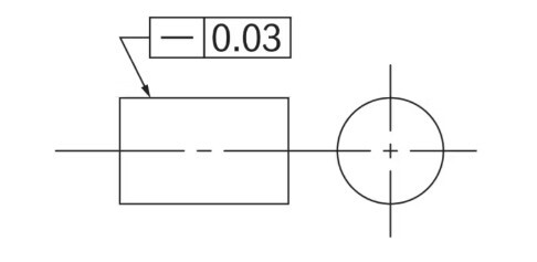
Surface straightness evaluates individual line elements along a surface, ensuring each measured element remains straight within the specified tolerance.
Axial Straightness
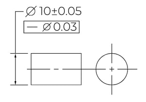
Axial straightness, on the other hand, controls the derived median line of a feature such as a shaft or hole, limiting how much the axis may bend or wander from a perfectly straight condition.
By controlling either the surface profile or the feature axis, straightness helps ensure predictable performance in applications involving linear motion, precision fits, sealing surfaces, and rotating components.
Tolerance Zone
Surface Straightness
When straightness is applied to a surface, the tolerance zone consists of two parallel lines separated by the stated tolerance value. Every point along the evaluated surface element must lie within these boundaries. The orientation of the zone follows the direction of the line element being inspected, allowing localized deviations such as bowing or waviness to be controlled without reference to any datum.
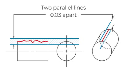
Two parallel lines on either side of a surface line where the surface must lie (2D).
This type of straightness control is commonly used on guideways, sealing surfaces, and machined edges where a straight line contact condition is critical. Because each line element is evaluated independently, surface straightness addresses the quality of individual cross-sections rather than the overall shape of the surface.
Axial Straightness
When straightness is applied to the derived axis of a feature of size, the tolerance zone becomes cylindrical. The derived median line of the feature must remain entirely within an imaginary cylinder whose diameter equals the specified straightness tolerance. This requirement limits the amount of axis curvature while allowing local size variations that remain within the applicable size limits.
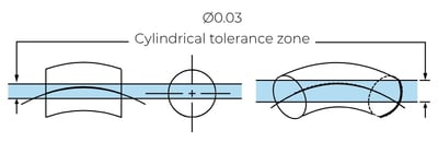
A cylindrical boundary around the true central axis of the part, where the derived median line of the part must fit into.
Axial straightness is frequently specified for shafts, pins, holes, and other cylindrical features where proper alignment or smooth rotational motion is required. By controlling the axis rather than the surface itself, designers can ensure that components function properly in assemblies even when minor surface irregularities are present.
How to Measure
The appropriate measurement method depends on the type of straightness being evaluated, the required level of accuracy, and the inspection resources available.
-
Surface straightness is commonly verified using a height gauge on a precision surface plate. The part is positioned to establish a stable reference condition, and multiple measurements are collected along the evaluated line element. By comparing the highest and lowest measured points, inspectors can determine whether the surface remains within the specified straightness tolerance.
This method is widely used in production environments because it is relatively simple, cost-effective, and suitable for many machined features that require moderate precision verification.
Secure the target so that the height is evenly matched on the left and right, using small jacks in order to prevent the target from tilting. Move the target or the height gauge straight to measure the straightness.
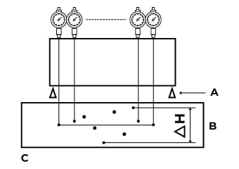
The difference between the maximum and minimum values (△H) is the straightness.
Inspection Limitations
In general, height gauges have lower precision than coordinate measuring machines. In addition, measured values can change with the force used to place the measuring part of the height gauge on the target, causing the measurement results to become unstable. With targets that cannot be placed level, the height gauge cannot be moved, which makes measurement difficult.
-
For higher accuracy requirements or complex geometries, a coordinate measuring machine (CMM) can evaluate both surface and axial straightness. The CMM collects a series of discrete points along the feature and uses software algorithms to construct the measured line or derived axis. The resulting data can then be analyzed against the specified tolerance zone to determine compliance.
A coordinate measuring machine can measure straightness by the operator simply putting the stylus lightly on the target. Thanks to this feature, there is almost no error caused by measurement pressure, and stable measurement results can be obtained.
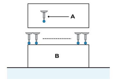
Because a CMM provides detailed geometric information and repeatable measurements, it is often the preferred method for precision components and first-article inspections.
-
Axial straightness of cylindrical features can also be evaluated using cylinder gauges, rotary inspection equipment, or dedicated straightness measuring systems. These instruments are designed to assess how closely a shaft or hole axis follows a straight path by detecting deviations from an ideal centerline.
To gage axis straightness effectively, the MMC modifier is sometimes called out on the drawing. To ensure that a part or feature is axially straight, a cylinder gage is used to determine if the part fits in its total envelope at MMC.
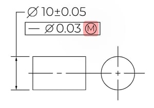
This controls the combined effect of the diameter and of the axial straightness. The ID of the cylinder gage represents the maximum virtual condition of the part.
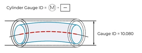
Specialized gaging solutions are particularly useful in high-volume manufacturing environments where rapid inspection and process monitoring are necessary. They provide an efficient means of verifying straightness while minimizing inspection time and operator variability.
Bonus Tolerance
When a functional gage is used to measure axis straightness, the straightness tolerance can have bonus tolerance added when the part diameter is smaller than MMC. The goal of a maximum material condition callout is to ensure that when the part is in its worst tolerances, both straightness and dimensionally, that the part will always fit a given size hole. This means that if you make a part smaller in OD, you gain bonus tolerance and can actually have it be less straight.
Remember – the goal of this callout is functional: The part must fit in a specific envelope.