Reducing Part Cost with GD&T
Hidden costs arise when tolerances ignore function and manufacturability, leading to over‑constrained geometry, conservative assumptions, and unclear inspection requirements.
When tolerances are aligned with function instead of idealized geometry, manufacturing flexibility increases, inspection becomes more efficient, and overall part cost declines without sacrificing performance.
Key Cost Drivers
Before examining how GD&T reduces cost, it’s important to understand where part cost actually originates.
Manufacturing cost is not driven solely by material selection or process choice; it is largely determined by how variation is constrained, interpreted, and managed throughout design, production, and inspection.
Many cost drivers are not explicitly visible on a drawing, but they are created the moment tolerances are applied without regard for function or manufacturing reality. These hidden costs accumulate through over‑constrained geometry, conservative manufacturing assumptions, and ambiguous inspection requirements.
Understanding these drivers provides the necessary context for why GD&T, when applied correctly, is not an added layer of complexity but a deliberate mechanism for removing cost from the system.
Over-Constrained Geometry
One of the most common and costly problems in traditional drawings is over‑constrained geometry. Plus/minus tolerances appear straightforward, but they impose multiple geometric constraints simultaneously. A linear tolerance applied to a feature of size does not merely control size; it also implicitly restricts form, orientation, and location. In many cases, this level of control is not functionally required, yet manufacturing must treat it as mandatory.
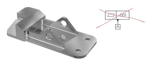
Let's use an example: consider a bracket. If that component's end-use is to be bolted or screwed into a final assembly, a flatness callout may be completely unnecessary. It's very common, though, for a machining partner to receive drawings with a tight tolerance flatness callout on a component like the one pictured above. What could be a simple component to machine all of the sudden becomes at risk for scrap due to an irrelevant feature that was tightly toleranced.
This leads to unnecessary precision. Features are machined more carefully than their function demands, additional finishing passes are added, and cycle times increase. Tool wear becomes a concern earlier than necessary, and process windows narrow. The end result is a part that is geometrically impressive but economically inefficient.
GD&T addresses this by allowing each geometric requirement to be controlled independently, ensuring that only functionally critical attributes consume manufacturing effort.
Hidden Manufacturing Constraints
Coordinate tolerancing also fails to communicate how a part is intended to be manufactured or assembled. Without defined datum structures, the drawing does not express which surfaces establish the functional reference frame or which relationships are critical to performance. As a result, manufacturing engineers and machinists are forced to infer design intent.
Inference introduces risk. To manage that risk, machinists default to conservative setups, additional fixturing, and extra operations to ensure compliance under worst‑case interpretation. Features may be re‑fixtured multiple times to chase location or orientation that was never functionally critical to begin with. These hidden constraints are not obvious on the drawing, but they are paid for in setup time, machine utilization, and labor cost.
Inspection Ambiguity
Inspection ambiguity is another significant cost driver associated with traditional tolerancing schemes. When a drawing does not define datums or measurement strategy, multiple inspection setups can be considered valid. Each setup may yield different results for the same physical part, particularly when form and orientation errors are present.
This ambiguity leads directly to false rejects, supplier disputes, and excessive inspection labor. Parts that would function perfectly in assembly are scrapped or reworked because they fail an interpretation‑dependent measurement. Quality engineers spend time adjudicating measurement disagreements instead of improving processes. GD&T reduces this waste by defining how the part is to be set up and evaluated, not just what numbers appear on the drawing.
These issues collectively affect several major cost categories:
- Machining time increases as tighter‑than‑necessary tolerances demand slower feeds and more passes
- Scrap and rework rise as parts are rejected for non‑functional deviations
- Inspection becomes more complex and time‑consuming
- Suppliers respond to ambiguity by adding risk premiums to their quotes
What appears on the drawing as a simple tolerance choice ultimately propagates through the entire value stream.
Cost-Reduction Mechanisms enabled by GD&T
Having established where cost is unintentionally introduced through traditional tolerancing practices, the value of GD&T becomes clearer when viewed through the mechanisms it enables rather than the symbols it employs.
GD&T does not reduce cost by simplifying drawings or relaxing requirements indiscriminately; it reduces cost by giving engineers precise control over how variation is allowed, managed, and verified across the manufacturing system. These mechanisms operate at multiple levels—design definition, inspection strategy, and supplier interaction—but they share a common goal: to remove unnecessary constraint while preserving functional intent.
Engineers and manufacturers actually have a shot at reducing cost when tolerances are chosen in light of real assembly conditions and manufacturing capability
Design-Driven Cost Reduction
A primary design‑level benefit of GD&T is the use of larger, more realistic tolerance zones. Geometric tolerances such as position, flatness, and profile define zones that reflect how parts actually function in assemblies. Cylindrical and planar tolerance zones allow variation in multiple directions simultaneously, which is far more manufacturable than stacked linear tolerances that constrain each axis independently. This increased freedom enables faster cycle times, reduced sensitivity to minor process variation, and higher overall yields.
Material condition modifiers further extend this benefit. By applying Maximum Material Condition to features of size, engineers allow additional geometric tolerance as material is removed. This “bonus tolerance” acknowledges that many functional requirements improve as clearance increases. Hole patterns, press fits, and clearance features benefit significantly from this approach, as parts that would otherwise be scrapped under fixed tolerances are accepted without functional risk. Over production volumes, the reduction in scrap and rework can be substantial.
Clear datum reference frames also reduce the need for secondary operations. When the drawing defines how the part is oriented and constrained relative to functional interfaces, manufacturing can plan efficient fixturing strategies from the outset. Re‑fixturing to chase ambiguous geometry is minimized, manual alignment is reduced, and corrective machining passes become the exception rather than the rule.
Inspection Cost Control
Inspection cost is often overlooked during design, yet it represents a meaningful portion of part cost in production environments. GD&T directly addresses this by making measurement requirements unambiguous. Datums specify how the part is to be set up, not just what dimensions are checked. This consistency eliminates interpretation differences between coordinate measuring machines (CMMs), functional gages, and shop‑floor inspection tools.
Because GD&T aligns naturally with CMM programming and functional gaging, inspection becomes faster and more repeatable. Programs can be reused across batches, gages can be designed with confidence, and statistical process control can be applied meaningfully.
Reduced inspection cycle time translates directly into lower cost per part, particularly in high‑volume environments.
Supplier Risk Reduction
From a supplier’s perspective, unclear drawings represent risk, and risk is always monetized. GD&T reduces this risk by explicitly communicating functional requirements. Suppliers no longer have to guess which features are critical or assume worst‑case geometry across the entire part. As a result, RFQs become more accurate, and quotes reflect actual manufacturing effort rather than contingency buffers.
Proper GD&T application also broadens the supplier pool. Shops that might avoid tightly coordinate‑toleranced work are often comfortable with GD&T when tolerances align with real manufacturing capability. Increased competition among capable suppliers further reduces cost while maintaining quality.
Engineering Takeaways
GD&T should be viewed as an engineering cost‑control lever rather than a precision mandate. It does not inherently tighten tolerances; instead, it enables intentional looseness where function permits and precise control where it is required. This selectivity is what drives cost reduction.
However, GD&T is not immune to misuse. Over‑tolerancing with tight profile or position controls applied universally can increase cost just as quickly as overly restrictive linear tolerances. Treating GD&T as a blanket upgrade in precision rather than a targeted communication tool defeats its purpose.
Datum structure selection is equally critical. Datums chosen for drawing convenience rather than functional interfaces force manufacturing into complex and expensive fixturing strategies. When datum schemes reflect real assembly conditions, GD&T simplifies production. When they do not, they introduce manufacturing gymnastics that erase potential savings.
Practically, engineers should apply GD&T only where function demands it and rely on general tolerances or title‑block defaults for non‑critical features. Position tolerances should be prioritized over coordinate dimensions, and profile controls should replace stacks of linear and angular tolerances wherever possible. Most importantly, tolerances should be validated against real manufacturing capability rather than theoretical ideals.
When used with this mindset, GD&T becomes more than a language for defining parts. It becomes a systematic way to reduce cost, improve manufacturability, and align design intent with production reality.