Datums and DRFs
A datum feature is the real surface you design and inspect; a datum is the ideal reference geometry derived from that feature.
When you strip GD&T down to its foundation, everything meaningful flows from a single idea: you cannot control or verify geometry without first defining what you are measuring against. That “what” is the datum system, and the structured expression of it is the Datum Reference Frame (DRF).
Datums solve three persistent engineering problems:
- Ambiguity in drawings – GD&T and datums provide a common language across design, machining, and quality teams
- Inconsistent inspection results – the DRF defines exactly how to orient and measure the part, eliminating interpretation
- Assembly failures – datums tie tolerancing to function, ensuring the part fits, aligns, and performs under load
Below is a disciplined, engineering-centric breakdown of what mechanical engineers should truly understand about datums and DRFs—not just academically, but in a way that drives better designs, cleaner drawings, and fewer shop-floor disputes.
Before diving into the details, let’s tackle a common misunderstanding – the difference between a datum and a datum feature.
Datum
A datum is a theoretically exact point, axis, line, plane, or combination that’s derived from the theoretical datum feature simulator. The most important thing to remember about datums is that they are theoretically exact.
Datum Feature
A datum feature is a real part feature (e.g., face, edge, hole, etc.) that’s identified with either a datum feature symbol or a datum target symbol. Datum features are not theoretical.
Datums are often conflated with physical part features; this is a mistake. A datum feature is what you design, machine, and inspect; a datum is a theoretically exact point, axis, line, or plane that exists only as a perfect reference.

This distinction matters because manufactured parts are inherently imperfect. Datums allow you to compare imperfect reality to a theoretically perfect model.
Understanding the DRF Coordinate System
The most effective way to understand datums is within the context of a coordinate system, the group of three mutually perpendicular datum planes that constrain how your part is machined, inspected, and assembled. This coordinate system is known as the datum reference frame.
Datum Reference Frame
A datum reference frame (DRF) is made of primary, secondary, and tertiary datum planes that serve as the reference for a component's location, orientation, and form relationships.
The DRF and datums define the degrees of freedom and constrain the part, and the sequence of datum features you choose directly relates the part to the DRF. This is commonly referred to as the 3-2-1 rule, which defines the number of points of contact required to establish the primary, secondary, and tertiary datum planes.

| Datum Level | Typical Constraint | DOF Constrained |
| Primary (A) | 3-point contact surface | 3 DOF |
| Secondary (B) | Edge or face | +2 DOF |
| Tertiary (C) | Perpendicular face/feature | +1 DOF |
A properly constructed DRF must contain these DOF in a defined sequence:
Datum A
Datum A is the first to make contact and requires at least three points of contact. In the example below, Datum A constrains the Z axis, or translation, and the U and V rotations along the X and Y axes, respectively.
Datum B
Think of this as the secondary datum, which corresponds to the secondary plane. Datum B requires two points of contact and constrains the Y axis and the W rotation along the Z axis.
Datum C
This functions as the tertiary datum and corresponds to the tertiary plane. Datum C is the least important, although not irrelevant, of the datums and has only one point of contact. In the example below, it only constrains the X axis.
How to Choose your Datums
The most practical thing to know about datums is that they must reflect function—not convenience. Before discussing datum selection strategy, let's walk through the types of datums that are at an engineer's disposal.
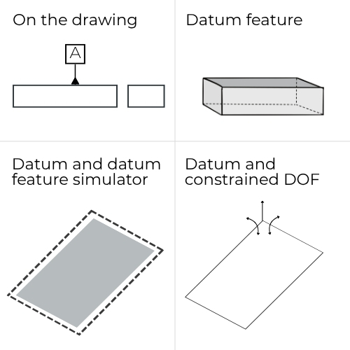
Planar Datums
Typically form the primary datum, establish 3 DOF (2 rotations + 1 translation)
- Derived from flat surfaces (e.g., machined faces, mounting pads)
- Used for primary, secondary, or tertiary datums
- Provide the most stability and repeatability in inspection
Example
Base plate surface = Datum A (primary plane)
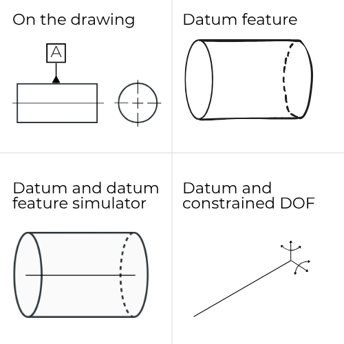
Axial Datums
Often used as secondary or tertiary datums; controls radial positioning and orientation
- Derived from cylindrical features (e.g., holes, pins, and shafts)
- Creates a datum axis
Example
Hole pattern centerline = Datum B (axis)
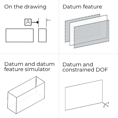
Center/Median Plane Datums
The datum is a plane, but it's derived from a size feature (i.e., not a single surface)
- Derived from features of size with two parallel surfaces
- Represent midpoints between opposing faces
- Provide the most stability and repeatability in inspection
Example
Slot or width feature establishes a medium plane datum
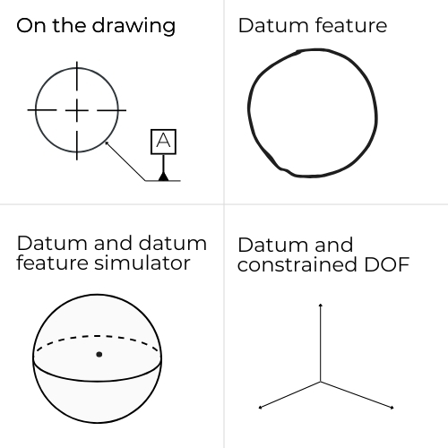
Point and Line Datums
Used for specialized applications, such as datum targets, complex fixturing, and aerospace/freeform geometries
- Rare as primary datums due to limited stability
- More often used as datum targets or constraints rather than full DRF builders
Example
Specifying datum targets A1, A2, and A3 on a bracket with a rough casting surface
A well-selected datum mirrors how the part interfaces in the final assembly, represents critical functional surfaces, and provides stable, repeatable inspection setups, and a well-designed DRF replicates how the part behaves in the assembly.
For example:
- A mounting plate → primary datum = mounting surface
- A shaft → primary datum = axis of rotation
- A housing → primary datum = interface face
This alignment ensures that tolerances directly control functionality, inspection replicates real-world use, and suppliers don’t “pass bad parts” that fail in assembly.

...
Engineering Takeaways
With regard to datums and DRFs, the selection is less about what's allowed and more about what reflects functional assembly conditions:
- Use planar datums for stability and fixturing fidelity
- Use axes when rotational alignment or concentricity drives function
- Use median planes when symmetry matters (e.g., slots, tabs)
- Avoid abstract datums (e.g., points or lines) unless absolutely required