Skip to content


Certifications ISO 13485:2016 | AS9100D | ITAR | FDA Registered | CAGE Code 5TTR7 


Optimize your Technical Drawings

In this guide, we go through the components of a technical drawing, practical steps for building an optimized drawing, types of dimensions and tolerances, best practices, and other guidelines to improve the communication between engineer and manufacturer.

Table of Contents

Overview   |   Anatomy   |   Drawing Features   |   How To   |   Best Practices   |   FAQ

Overview

In today's CNC machining, the process begins with a 3D CAD model made using specialized software. This model is transformed into G-code through CAM software, which CNC machines use to craft the part from raw material. The 3D CAD file contains all the essential details needed for the CNC machine to produce the part.

Technical drawings provide detailed 2D images of a part and include essential manufacturing data. They ensure that the designer and machinist clearly understand the project's technical requirements.

Often, machinists can create a part using just a technical drawing. In CNC machining, these drawings are essential companions to 3D models. 
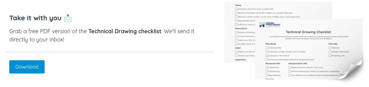
This guide will explain why technical drawings are important, what they include, and how to create an ideal technical drawing step-by-step.


Sidebar Subscribe CTA (2)

Anatomy of a Technical Drawing

Title Block

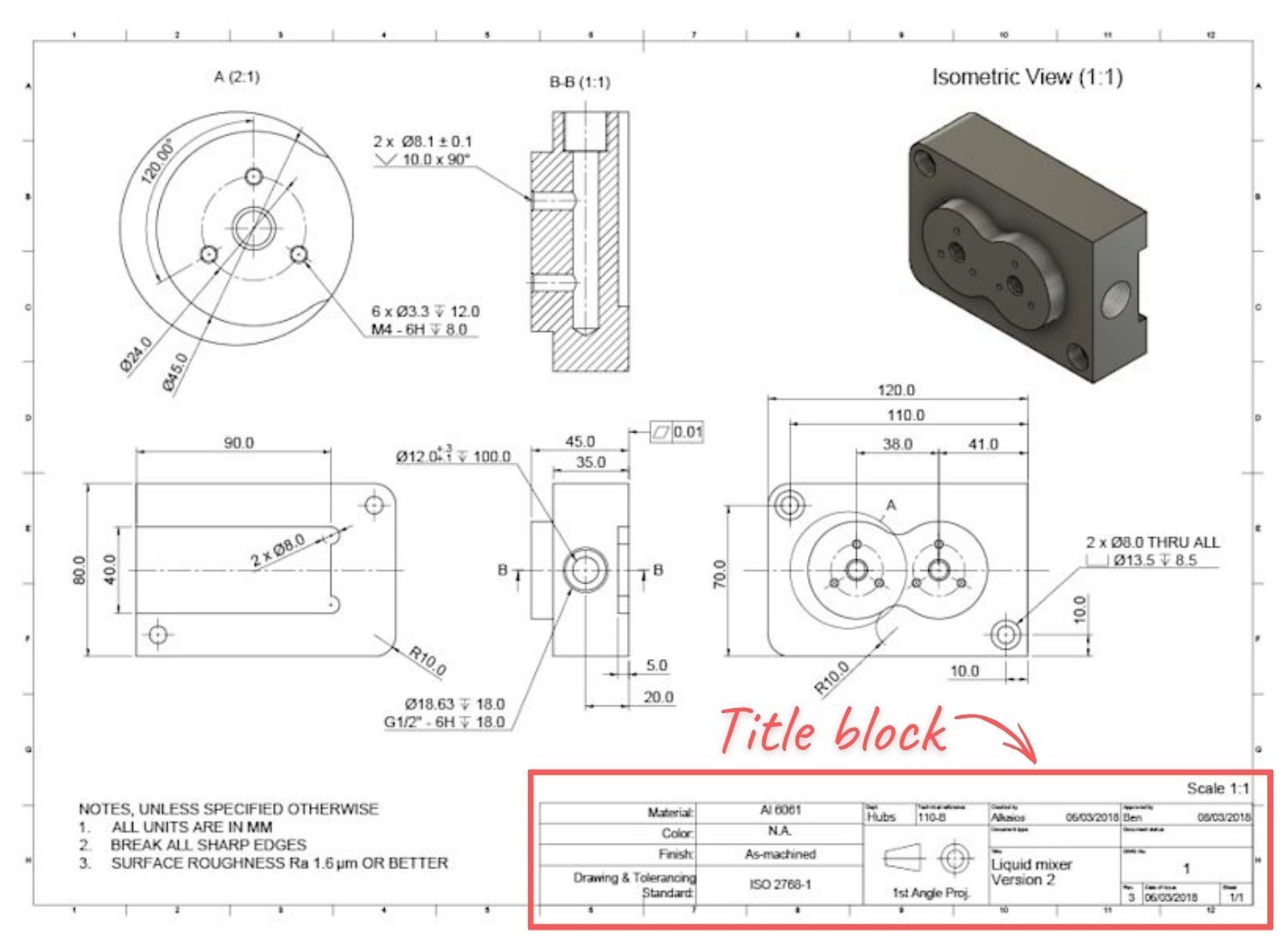
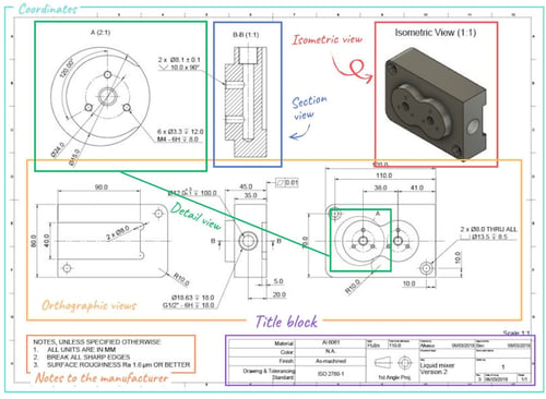
The title block is in the bottom right corner of the document. It includes essential details like the part name, the names of the team members involved (design, checking, and approval), and the company name.

It includes technical details like measurement systems, projection angles, surface finish needs, scale, and material. The title block template can be standard or custom.

Title Block

Coordinates

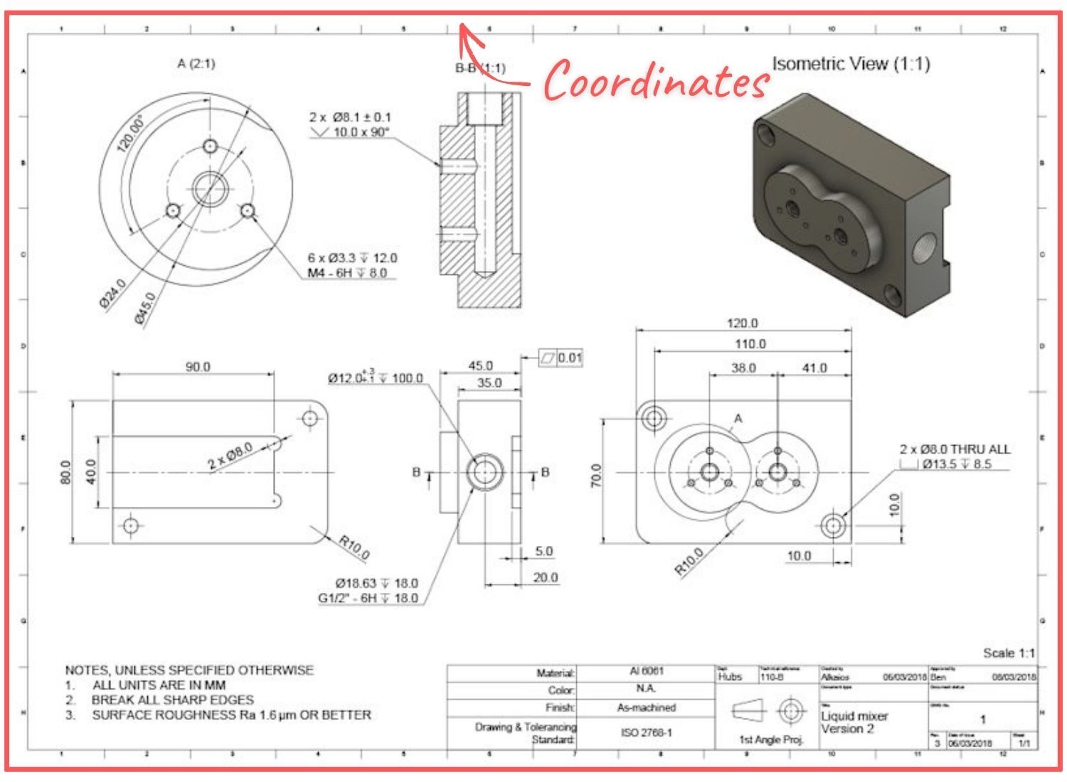
Coordinates are typically found along the edges of large or complex technical drawings. They act as reference points for discussing the drawing's details.

Coordinates

Isometric View

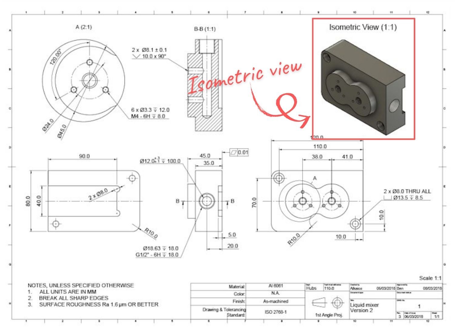
An isometric view is a 3D image of a part. Including it in a technical drawing is often helpful, as it makes it easier for machinists to understand the part's shape. It also provides details like how to install the part and its build orientation.
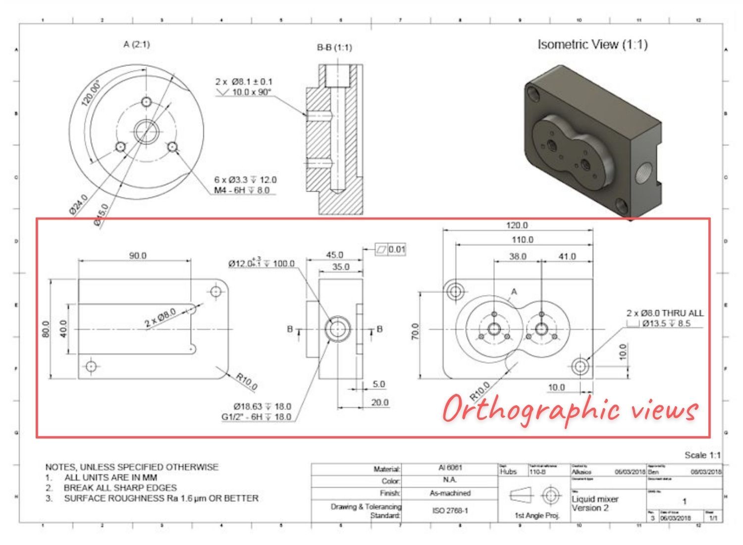
Isometric View

Orthographic Views

Orthographic views provide key details about a part's shape. They include most of the dimensions and tolerances. These are 2D images of a 3D object, viewed from the front, top, and side.

Hidden lines can be added to orthographic views to show important features that aren't visible. Usually, two or three orthographic views are sufficient to accurately represent a part's entire geometry.
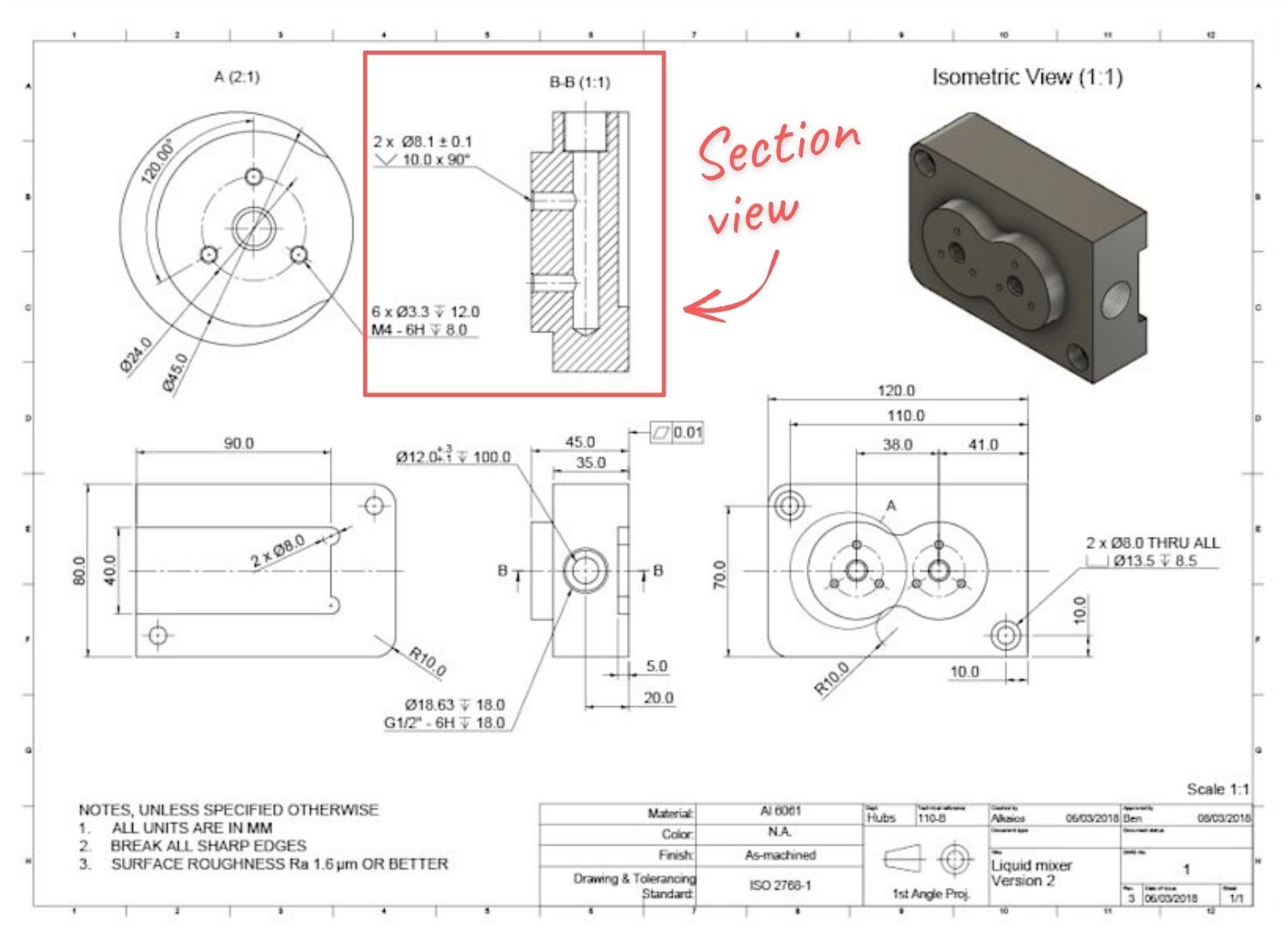
Orthographic Views

Section View

A section view is a 2D image showing the inside of a part when it's cut open. It reveals internal features not visible in isometric or orthographic views and is typically aligned with an orthographic view.

In the orthographic view, a labeled cutting line indicates where the part is sliced to create the section view and shows the cut's direction. Section views have crosshatch patterns to highlight where material was removed. Complex parts might have multiple section views.
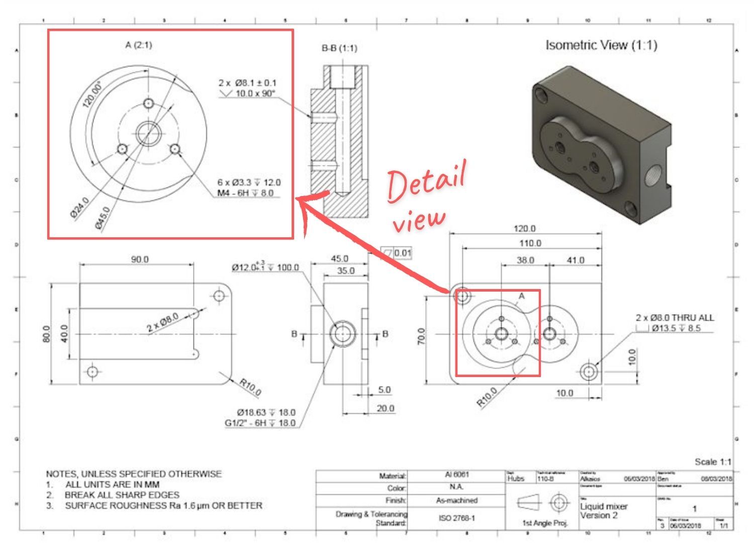
Section View

Detail Views

When an orthographic view has complex areas that are hard to measure, detailed views are used to focus on these parts. These detailed views can be any size and placed anywhere in the drawing. They are marked with a single letter indicating which part of the orthographic view is being detailed.

Detail Views

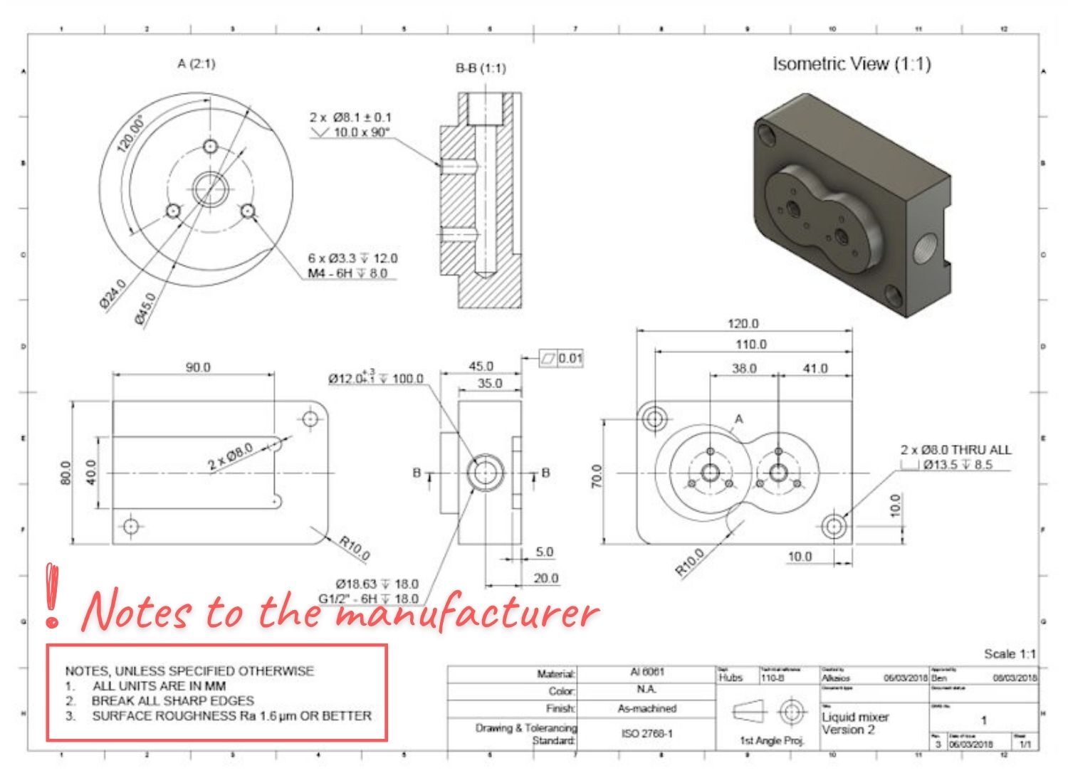
Notes to the manufacturer

Manufacturer notes are typically found at the bottom left of the technical drawing or above the title block. They provide extra details not shown in the drawing and give instructions for the machinist. These notes might include directions to break and deburr sharp edges, specify surface finish requirements, or list other components to be assembled with the part.

Notes to the Manufacturer

Technical Drawing Features

Types of Dimensions and Tolerances

Engineering drawings must at least have dimension callouts on key features, along with their tolerances. These dimensions guide manufacturers on what to measure during inspection and the acceptable limits for each feature. Most drawings use a mix of different dimension types.
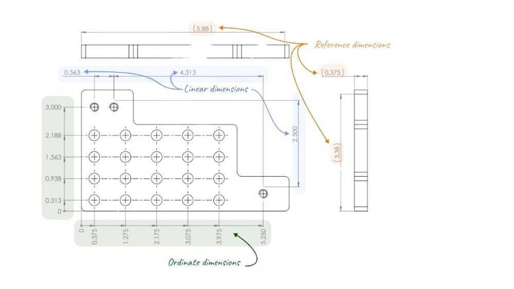
Types of Dimensions (1)

Ordinate Dimensions

Ordinate dimensioning measures the distance from a reference point (zero) to multiple features. The dimension is shown parallel to and at the end of specific extension lines. This method is ideal for positioning groups of features, like hole patterns, in relation to a main reference point.

Linear Dimensions

Linear dimensioning measures the distance between two features, shown between two lines extending from a part view. It is effective for clearly defining critical dimensions and tolerances. However, using too many linear dimensions can cause clutter if lines and arrows overlap.

Reference Dimensions

Reference dimensions provide additional information and are not used to specify critical geometry. They are usually shown with parentheses around the dimension value. A common use of reference dimensions in part drawings is to indicate the total part size (bounding box) by referencing the largest dimension in each orthographic view. This helps machinists quickly determine the stock material size needed for the part.

Types of Tolerances (1)

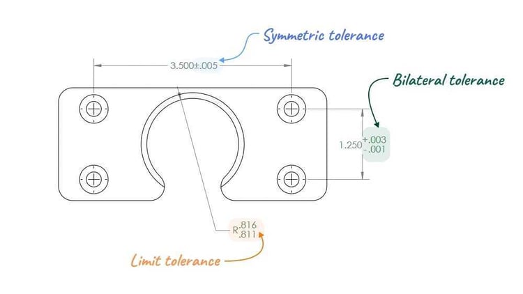
Symmetric tolerances define a range with equal limits above and below the target dimension (e.g., 1.000”±0.005”).

Bilateral tolerances are similar to symmetric tolerances, but they are not centered on the nominal dimension (e.g., 1.000” +0.003” / -0.001”).

Limit tolerances avoid using the ± symbol and instead clearly state the maximum and minimum values for a dimension.

Related Read: 10 GD&T Best Practices from our Engineers

Types of Views

Drawing views serve one purpose: to convey 3D geometry in 2D. Ensure your drawings have enough views for anyone to easily understand the 3D part. Even if you provide both a 2D drawing and a 3D file to manufacturers, it's best to treat the drawing as a standalone document for clarity and completeness.

Types of Views

Basic Views

Include a main view, usually the front view, along with one or more orthographic views. Add an isometric view, or choose dimetric or trimetric based on the part's geometry. This is shown below with a simple machined component.

Section Views

You can add extra projected and section views to display geometry not visible in other views. A section view is a slice of the part, shown at a specific plane, with dashed lines and arrows indicating the direction. This is ideal for detailing complex hole designs, such as stacked precision bores with snap ring grooves.

Detail Views

Detail views enlarge specific features to improve clarity and readability of dimensions. Common machined features like O-ring and snap-ring grooves are best shown using both section and detail views to clearly convey their geometry. This approach allows you to add dimensions and notes to smaller features without overcrowding the main view.

Auxiliary Views

Auxiliary views are additional views that help show features or geometry not easily seen in standard orthographic views. Use them for features that don't align with the main views.

Types of Lines

Solid lines show the outer edges and surfaces of parts.

Break lines indicate where a view is shortened to make key features easier to read. They help fit long features like shafts, rods, and beams into smaller drawing spaces by allowing precise dimensioning. This is especially useful for parts with a large length-to-width or thickness ratio, as it improves the overall clarity of the drawing by enabling the use of smaller sheet sizes.

Hidden lines show parts of a design that are blocked by other features.

Hatch lines usually show the cut surfaces in a section view. They can also highlight specific areas on a face that need extra specifications. Use hatch lines in section views or to mark a face related to a surface finish callout.

Center lines indicate the middle point between features or show symmetry related to one feature.

How to Build the Perfect Technical Drawing

Modern manufacturing starts with a 3D CAD model. Most 3D CAD software includes a technical drawing interface that lets you easily create drawings from existing models. This interface provides all the tools needed to create views, add annotations, dimensions, and apply tolerances, so you don't have to design views from scratch.

You can also use software to create technical drawings without needing a 3D model.

Here are the steps and tips to create an ideal technical drawing.

  1. Identify the key views and position the main orthographic view at the center of the drawing, ensuring there is ample space around them for adding dimensions.
  2. If your part has internal features or areas that are hard to measure, consider adding section or detail views.
  3. Add lines to all views. Use construction lines like centerlines to define symmetry, and center marks and patterns to locate the centers of holes or circular patterns.
  4. Add the most critical dimensions to your CNC drawing.
  5. Indicate the position, dimensions, and length of each thread.
  6. Apply precise tolerances to features requiring greater accuracy than standard. Complete the title block and include any extra information or requirements beyond standard practices, such as surface finish and deburring, in the additional notes

Free Resource: Technical Drawing Checklist   

Best Practices

There is no exhaustive list of best practices to implement into your technical drawings, but we’ll leave you with a few final tips and guidelines to keep in mind.

Call out features that are “inspectable”

Just as dimensions are based on function, inspections are based on dimensions. A drawing with clear dimensions between functional parts not only shows clear design intent but is also easier and cheaper to inspect. The closer the inspection measurements are to functional parts, the less likely a part will pass inspection but fail in function. Always aim for a direct link between inspectability and functionality.

Dimension what you can measure

Similarly, ensure you dimension the physical features of your part. Avoid using non-measurable datums. Whenever possible, dimension to a physical feature instead of a part centerline or CAD modeling plane. Centerlines and center planes require inference from other geometry during inspection, which can complicate in-process inspection steps. An exception to this is hole centers.

By dimensioning in this manner, you guide the manufacturer on which features and surfaces require special focus and which are less critical. Identifying what is less important can save significant manufacturing time by allowing for more lenient tolerances and quicker production in non-essential areas.

Leave very clear notes for the manufacturer

Be clear and specific in your drawings. A brief note explaining a feature's purpose helps machinists and fabricators make informed decisions during programming, setup, and manufacturing.

Convey design intent as clearly as possible

This is by no means exhaustive, but here are a few quick tips for making clear and legible drawings.

  • Don’t cross dimension lines and don't dimension hidden lines
  • Employ ordinate dimensions whenever possible
  • Use as many section views, detail views, and pages as necessary to convey manufacturing intent without ambiguity, but no more than that (we know – a tough needle to thread!)
  • Write clear and straightforward notes. These notes should resolve any confusion in the drawing or provide additional details to express design intent, such as drill bit size, form tap hole, or ream to fit.
  • Use the space you have to add appropriately scaled projected views
  • Include an un-dimensioned isometric view. This view helps communicate 3D at a glance and can be different than the drawing scale used in all other views.


Our team of engineers and manufacturers takes technical drawings very seriously. They are essential for creating an efficient, cost-effective, and reliable manufacturing process, and they play a key role in transitioning from design to production. Don't underestimate this step in hardware product development.

We hope this information is helpful!

Frequently Asked Questions

What are the key elements of a well-prepared part drawing?

A well-prepared part drawing should clearly show dimensions, tolerances, material details, surface finish needs, and any special instructions. It must also have a detailed and easy-to-read layout.

Why is it important to include tolerances on a part drawing?

Tolerances define the acceptable range for dimensions and shapes, ensuring parts fit and work properly. Adding tolerances to part drawings ensures the final product is consistent and high-quality.

How can I ensure that my part drawing is easy to read and understand?

For clarity, follow standard drawing practices, use straightforward annotations, and organize logically. Keep it tidy, and make sure all measurements and notes are easy to read and understand.

What role do material specifications play in part drawings?

Material specifications tell us what material to use for the part. This is essential for choosing the right machining settings and making sure the final product performs as needed.

How can I optimize the layout of my part drawing?

Arrange the layout logically, using the right scales, and make sure all important features are easy to see. Show multiple views (like top, front, side) and detailed views for complex features.

What are some best practices for dimensioning in part drawings?

For effective dimensioning, use the same units throughout, place dimensions outside the part outline, avoid unnecessary dimensions, and use reference dimensions for clarity. Clearly mark all critical dimensions.

How can I indicate surface finish requirements in part drawings?

Use standard symbols and notes to show surface finish needs. Indicate the required surface roughness (like Ra value) and any special finishing methods (such as polishing or anodizing).

What is the importance of including special instructions in part drawings?

Special instructions offer extra details not included in standard dimensions and annotations. These may cover assembly steps, inspection needs, and specific machining techniques.

How can I ensure that my part drawing is compatible with CNC machining?

Follow standard drafting practices, use precise dimensions, and avoid complex features that are hard to machine. Work with machinists to ensure the design is feasible.

What are common mistakes to avoid when creating part drawings for CNC machining?

Ensure your drawings are accurate by checking for common errors like missing or unclear dimensions, inconsistent tolerances, lack of material specifications, and cluttered layouts. Review and validate your drawing thoroughly before submitting it.

Homepage

Let's connect

Want to learn more about our CNC machining services? Schedule a time to speak with our team.