
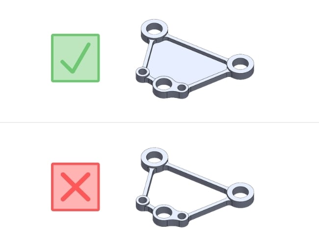
What is GD&T?
Geometric dimensioning and tolerancing (GD&T) is a system that communicates design intent through an engineering drawing and defines the desired dimensions and tolerances of manufactured parts.
Updated: 8/18/26
Why is GD&T important?
GD&T uses a symbolic language on engineering drawings and 3D models to describe geometry and its variations. This ensures parts and assemblies are made consistently and accurately.
GD&T follows the ASME Y14.5-2018 standard, which details how to control part geometry in technical drawings.
Benefits of using GD&T:
- Standardized language that conveys design intent
- Precise communication between engineers and manufacturers
- Method for calculating the worst-case mating limits
- Repeatable production and inspection processes
- Assembly is assured from qualified production parts
Essentially, GD&T is a set of rules and symbols that create a language for defining geometry and its variations. You don't need to memorize every symbol, but it's important to understand the basic framework of how it works
How does GD&T work?
GD&T communicates design intent in ways that basic coordinate dimensions and tolerances cannot. It does this by defining how a part’s size, location, form, and orientation must relate to each other and then applying the right geometric controls.
.jpg?width=750&height=401&name=GD%26T%20feature%20categories%20(1).jpg)
Size is the actual physical dimension of a feature. It is usually controlled with standard ± tolerances, although profile can also be used to control size.
Location is where a feature sits in 3D space relative to other features on the part. In GD&T, this is most often controlled with the Position tolerance.
Orientation describes how a feature is angled in 3D space relative to other features. It further refines location and is typically controlled with Parallelism, Perpendicularity, or Angularity, though other symbols, such as Runout, can also influence orientation.
Form describes the basic shape of a feature. Form controls such as straightness, flatness, circularity, and cylindricity are used as final refinements and are applied only when they are functionally necessary.
Size, location, form, orientation, and geometric controls all come together in the technical drawing.
What is a technical drawing?
A technical drawing, also known as an engineering drawing, is a 2D representation of a machined component that communicates design intent clearly. It ensures that everyone involved in the manufacturing process understands the exact requirements and can produce the part to the specified standards.
A typical technical drawing includes several key components:
- Views – different perspectives of the part, such as front, top, side, and isometric views
- Dimensions – measurements that specify the size and location of features on the part
- Tolerances – allowable variations in dimensions to ensure proper fit and function
- Notes – additional information, such as material specifications, surface finish requirements, and assembly instructions
- Symbols – standardized symbols used in GD&T to indicate geometric characteristics and controls
Technical drawings are crucial in the manufacturing process because they provide a clear and standardized way to convey complex information. Acting as a universal language for engineers and machinists, they ensure that parts are made correctly by providing all the necessary information produce and inspect parts accurately. The more detailed, the better.
What is a feature control frame?
A feature control frame (FCF) is a rectangular box that contains the geometric characteristic symbol, tolerance value, and any additional modifiers or datum references. It is used to define the allowable variation in the geometry of a part feature, such as its form, orientation, location, or profile.
FCFs play a critical role in GD&T. They provide a standardized way of specifying geometric characteristics and tolerances of a part feature, ensuring that the part meets the required designed specifications.
A typical feature control frame includes the following components:
- Geometric characteristic symbol: indicates the type of geometric control, such as flatness, perpendicularity, or position
- Tolerance value: specifies the allowable variation in the feature's geometry
- Modifiers: additional symbols that provide further information about the tolerance, such as maximum material condition (MMC) or least material condition (LMC)
- Datum references: identifies the datums (reference points or planes) used to establish the tolerance zone
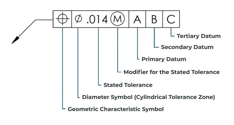
The first section of an FCF includes a geometric characteristic symbol. Each frame can hold only one symbol. If a feature has two requirements, use either two separate frames or a composite tolerance. The symbol indicates the type of control applied to the feature.
GD&T symbols are organized into tolerance groups, including form, orientation, location, and runout.
What are Form Tolerances?
Form tolerances control the "shape" of features and are often used to refine size, meaning they do not require a datum reference.
- Straightness - controls the deviation of a line on a surface or an axis within a tolerance zone that is defined by two parallel lines a distance apart; no datum required
- Flatness - holds a plane within a given tolerance zone defined by two parallel lines; no datum required
- Circularity - also known as roundness, it controls deviation from a true circle; the tolerance zone is the space between two concentric circles
- Cylindricity - controls deviation from a cylinder; while similar to circularity, the tolerance zone is between two concentric cylinders
What are Orientation Tolerances?
Orientation tolerances control the "tilt" of features, link to basic angle dimensions, and refine location. Because orientation in GD&T is relative, these feature control frames always reference a datum. When applied to surfaces, orientation tolerances manage form.
- Angularity - controls the angle between two surfaces, with two parallel planes (both at the required angle to the datum feature) acting as the tolerance zone
- Parallelism - controls parallelism between two parallel surfaces, with two parallel planes (both parallel to the datum feature) acting as the tolerance zone
- Perpendicularity - controls perpendicularity between two 90-degree surfaces, with two parallel planes (both perpendicular to the datum feature) serving as the tolerance zone
What are Location Tolerances?
Location tolerances control the location and are linked to basic linear dimensions. Location GD&T can position a feature or its size based on the feature itself or a set of derived median points. These characteristics are highly versatile and powerful, allowing control over size, form, and orientation within a single feature control frame.
- True Position - controls how far a feature of size can deviate from where it should be; the acceptable area is generally defined by a circular or cylindrical tolerance zone
- Surface Profile - a 3D tolerance zone that defines where the surface needs to be located; it can also be applied to curved surfaces
- Line Profile - a 2D tolerance zone that defines the profile along a 2D cross-section of a surface
What are Runout Tolerances?
Runout tolerances control the functional and rotational accuracy of a part feature, usually cylindrical or rotational parts, by limiting how much a surface or feature can deviate as it spins around a datum axis.
- Total Runout - controls the acceptable variation in a surface when it’s rotated 360 degrees around a central axis (the datum feature); the tolerance zone is defined by two concentric cylinders
- Circular Runout - the 2D version of Total Runout
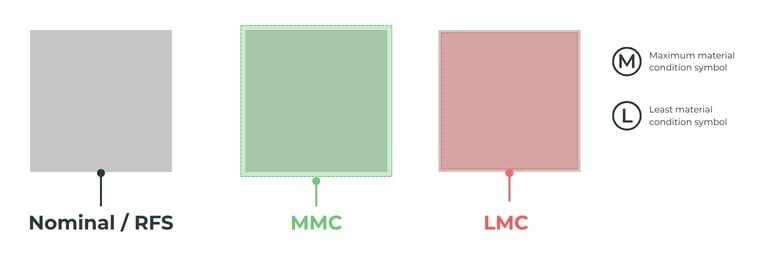
After the feature tolerance in the FCF, you might see a material condition modifier like Max Material Condition (MMC) or Least Material Condition (LMC) for features of size, such as holes.
Engineers use MMC, LMC and RFS to specify that a tolerance is linked to a feature’s size.
- Maximum Material Condition (MMC) - the condition where a feature holds the most material possible within specified size limits, such as the largest pin or the smallest hole
- Least Material Condition (LMC) - the condition where the feature contains the least material within the stated limits of size. (ex: smallest pin and/or largest hole)
- Regardless of Feature Size (RFS) – the default setting of a feature control frame means the geometric control applies no matter the size or shape variations of other part features
These material condition modifiers are placed in a feature control frame after the feature tolerance. Using MMC and LMC modifiers allows for extra geometric tolerance, known as "bonus" tolerance, when features move away from the specified condition.
If no modifier is specified, the default is RFS (Regardless of Feature Size), though it's not shown in the frame. For non-size features, like plane surfaces, these modifiers aren't used.
The remaining sections of the feature control frame will include datum feature references if needed. For instance, if a form tolerance like flatness or straightness is specified, no datum reference is used. Conversely, if a location tolerance, such as position, is specified, datum references are typically included.
The order of datum references is based on their importance, not the alphabet. They are read from left to right as primary, secondary, and tertiary, and typically read Datum A as the primary, followed by B and C.
How does GD&T reduce part cost?
GD&T is often treated as a documentation standard or a compliance requirement, but that framing misses its primary value. Fundamentally, GD&T is a control system. On the one hand, it controls design intent, which is critical for making sure parts are made correctly. On the other hand, it enables engineers to control, and even reduce, part cost.
Manufacturing cost is rarely driven by material alone. In most machined components, cost is dictated by
- How tightly the part must be controlled
- How clearly those controls are communicated to the people responsible for making and inspecting it
When applied strategically, GD&T allows engineers to specify exactly what must be controlled for function and, just as importantly, what does not. This selective control is where cost is removed from the system rather than added.
Traditional tolerancing methods tend to assume that closer to nominal is always better. GD&T challenges that assumption by asking a more useful question like “how much variation can this feature tolerate and still perform its role in the assembly?”
When tolerances are aligned with function instead of idealized geometry, manufacturing flexibility increases, inspection becomes more efficient, and overall part cost declines without sacrificing performance.
Key takeaways for engineers
Despite its intent, GD&T is often perceived as a way to make drawings more restrictive. This perception usually comes from poor application rather than from GD&T itself.
One of the most common failure modes in GD&T is starting with features instead of function. Engineers look at a drawing, identify holes, faces, and slots, and then ask, “What tolerance should I put here?”
That question is already backwards.
The correct starting point is always functional behavior in assembly:
- How is the part located?
- Which surfaces establish repeatability?
- Which features interface with other components under load?
- Which misalignments cause binding, leakage, or wear?
Only after those questions are answered does it make sense to decide how geometry should be controlled. Your tolerancing should be framed around assembly context and mating conditions, rather than isolated features because geometry divorced from function leads to over-constraint and unnecessary cost.
This functional framing also explains why two parts with superficially similar geometry can require radically different GD&T schemes depending on how they are used. A hole that locates a bearing in a rotating assembly is fundamentally different from a clearance hole for a fastener, even if the diameters are identical.
Properly applied, GD&T often loosens tolerances. By separating form, orientation, and location requirements, it allows engineers to stop over‑constraining features that do not impact function. This selective control is one of the primary economic benefits of GD&T, particularly in complex assemblies where tolerance stack‑ups dominate performance.
Another persistent misconception is that learning GD&T is primarily about memorizing symbols. This approach produces engineers who can decode a feature control frame but cannot decide when to use one. GD&T Basics explicitly criticizes this rote‑learning model, noting that standards familiarity without application context rarely translates into effective tolerancing decisions.
Finally, GD&T is not a substitute for good design. It cannot fix poor part architecture, unrealistic process assumptions, or undefined functional requirements. GD&T clarifies intent; it does not invent it.