
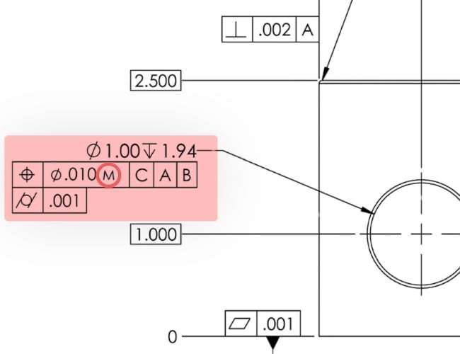
What is a Material Condition Modifier?
Material condition modifiers—MMC, LMC, and RFS—link geometric tolerances to feature size, helping control assembly fit and account for size variation.
Updated: 8/17/2026
Why are material condition modifiers important?
In CNC machining, MMC aligns geometric tolerances with actual feature size, improving efficiency without unnecessary constraints.
Material condition modifiers help engineers meet functional requirements while allowing more manufacturing flexibility and reducing inspection effort. They also adjust geometric tolerances based on feature size, helping manufacturing and inspection teams know when to tighten or relax them.
What are the fundamentals of material condition modifiers?
A feature of size inherently contains dimensional variability bounded by its tolerance limits. Material condition modifiers describe how geometric tolerance should behave across that dimensional range.
Consider a simple hole:
Example: Ø10.00 ±0.10 mm hole
Limits: 9.90 mm → 10.10 mm
This variation creates three distinct states and represents the three types of material condition modifiers: MMC, LMC, and RFS.
| Condition | Internal Feature (Hole) | External Feature (Shaft) |
| Maximum material condition (MMC) | Smallest size | Largest size |
| Least material condition (LMC) | Largest size | Smallest size |
| Regardless of feature size (RFS) | Not size-dependent | Not size-dependent |
Maximum Material Condition (MMC) indicates that the feature contains the most material. Consider the previous example—MMC would put the hole at the smallest size (i.e., 9.90 mm).
Least Material Condition (LMC) indicates that the feature contains the least material. Per the previous example—LMC would put the hole at the largest size (i.e., 10.10 mm).
Regardless of Feature Size (RFS), in addition to being the default if there’s no MMC or LMC, indicates that the geometry is independent of size.
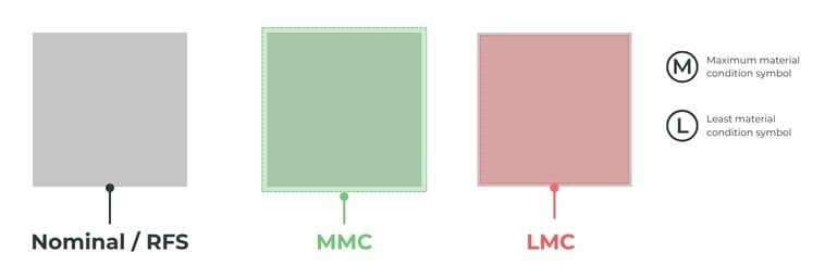
What is Regardless of Feature Size (RFS)?
Regardless of feature size (RFS) applies when no material modifier is specified. It is the default condition in GD&T. Under RFS, geometric tolerance is constant, regardless of size, and no bonus tolerance is permitted.
How does RFS appear on a drawing?
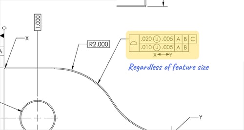
RFS is implicit—no symbol is shown. This absence often leads to unintended over-constraint when designers assume flexibility where none exists.
What is the role of RFS?
RFS enforces absolute geometric fidelity, ensuring performance criteria are met under all size conditions, and is appropriate to default to when:
- Geometry must be strictly controlled independent of size
- Functional performance is highly sensitive to location or orientation
- Clearance or material variation does not reduce risk
Appropriate applications include bearing alignment, precision mating surfaces, and high-speed rotating components.
What is Maximum Material Condition (MMC)?
Maximum Material Condition (MMC) describes the point at which a feature contains the greatest amount of material allowed within its size tolerance.
For a feature with a GD&T callout:
-
If it is a hole or internal feature: MMC = smallest hole size
-
If it is a pin or external feature: MMC = largest size of the pin
In each case, the part contains the maximum amount of material allowed within its specified tolerances.
MMC can only be applied to these GD&T controls: straightness (axis), parallelism, perpendicularity, angularity, and true position—the most common application.
How does MMC appear on an engineering drawing?
MMC is applied using the Ⓜ symbol within the feature control frame:
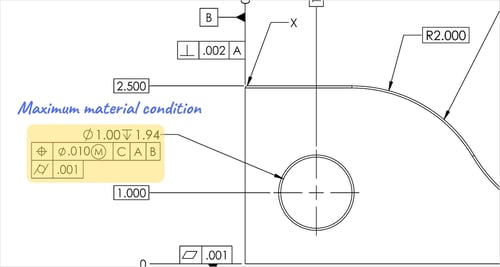
What is the role of MMC?
MMC helps prevent interference between parts at their worst-case tolerances, such as a shaft passing through a clearance hole.
- The MMC of the shaft would be the Maximum diameter
- The MMC of the hole would be its Minimum diameter
Keeping the shaft’s MMC smaller than the hole’s guarantees clearance, even at worst-case tolerances, so the assembly functions properly.
What is Least Material Condition (LMC)?
Least Material Condition (LMC) describes the point at which a feature contains the least amount of material allowed within its size tolerance.
For simplicity:
- If it is a hole or internal feature: LMC = Largest hole size (least material in part)
- If it is a pin or external feature: LMC = Smallest size of the pin
Least Material Condition defines one end of a part’s size tolerance range, while Maximum Material Condition defines the other.
How does LMC appear on a drawing?
LMC is indicated using the Ⓛ symbol.
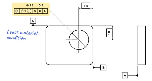
What is the role of LMC?
LMC is most often used when a hole or other internal feature is close to the part’s edge. It's also used when two parts must stay in contact or form a press fit, as it helps ensure a snug fit with no clearance.
Keeping the shaft’s LMC larger than the hole’s ensures a tight fit and enables functional gauging to catch undersized shafts or oversized holes.
Use LMC only when necessary because size and geometry cannot be gauged accurately at the same time. Its main purpose is to ensure enough material remains between a hole and the part’s edge.
How to inspect material condition modifiers?
Material condition modifiers shape inspection strategy. Poorly chosen modifiers can increase inspection costs, lead times, scrap, and validation complexity.
MMC supports scalable inspection, LMC protects structural integrity, and RFS enforces strict precision.
Let’s go through each modifier in more detail.
How to inspect regardless of feature size?
RFS requires the most rigorous inspection because size and geometry must be measured and satisfied independently.
RFS almost always requires direct measurement, typically via CMM:
- Feature size is measured independently
- Geometric deviation (position, form, orientation) is evaluated relative to datums
- No bonus tolerance is applied
RFS does not allow functional shortcuts such as virtual condition gauges. Each part must be inspected based on its measured geometry, increasing production and inspection demands.
| Production | Inspection |
|
Tighter machine calibration requirements Conservative cutting strategies Increased scrap or rework rates |
Increased inspection time per part Higher reliance on metrology expertise and programming Greater sensitivity to measurement uncertainty |
Use RFS only for features where geometric accuracy is critical, such as bearing bores and precision alignment interfaces.
How to inspect maximum material condition?
MMC supports efficient, function-based inspection by allowing geometric tolerance to expand as features move away from worst-case limits. Inspectors use virtual condition boundaries, go/no-go gauges, or CMMs.
Gauges
A GO gauge is manufactured to the virtual condition. If the part accepts the gauge under proper datum simulation, it is considered conforming. This method offers several advantages:
- It collapses multi-variable evaluation (size + geometry) into a single pass/fail check
- It directly reflects assembly functionality, rather than abstract geometric compliance
- It dramatically reduces inspection cycle time compared to full CMM routines
In high-volume CNC production, this approach is often the difference between inspection as a bottleneck and inspection as an enabler.
CMMs
When CMM inspection is used, the software must account for bonus tolerance. Modern metrology systems will:
- Measure actual feature size
- Calculate bonus tolerance automatically
- Expand the allowable positional error accordingly
CMM results match gaging only when virtual condition and bonus tolerance are applied correctly.
How to inspect least material condition?
LMC inspection focuses on material thickness and structural integrity, not assembly fit. Because failures can involve localized thinning, functional gaging is less straightforward than with MMC.
As a result, LMC inspection typically relies on:
- CMM measurement with boundary analysis (again, they must calculate bonus tolerance)
- Profile or form evaluation tied to minimum material envelopes
- Custom gaging (these are less common and more application-specific)
As a feature moves away from LMC and gains material, inspection becomes more permissive. The critical condition remains the largest allowable hole or smallest allowable shaft, where the part is weakest.
During machining, LMC inspection can reveal issues that may not appear during design or prototyping, including:
- Tool deflection creating localized thin spots
- Inconsistent stock allowance in deep pocketing operations
- Deformation during clamping
For this reason, LMC inspections are often used for process validation, not just final part acceptance.
Material condition modifier takeaways for engineers
Use material condition modifiers to assess worst-case fit while accounting for tool deflection, thermal growth, and fixturing.
- MMC matches tolerances to mating conditions, allowing more geometric variation where clearance exists while preserving fit and simplifying manufacturing and inspection.
- LMC protects thin or vulnerable areas by tightening control where material is low and allowing more tolerance where material is plentiful.
- Use RFS only where geometric variation affects function; unnecessary use increases manufacturing and inspection effort.
Used correctly and intentionally, MMC, LMC, and RFS turn GD&T into a tool for designing how parts assemble and perform.