
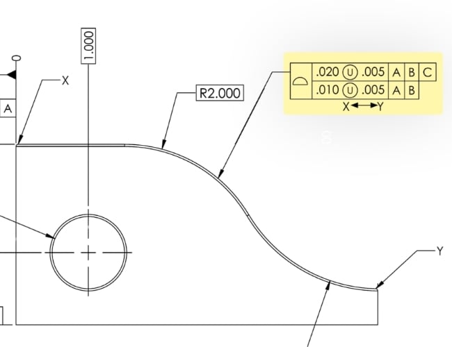
What is a Feature Control Frame?
Feature Control Frames (FCFs) are the standard way to communicate geometric tolerances, defining both the required values and the spatial relationships that control how a part functions in an assembly.
Updated: 8/19/26
Why are feature control frames important?
Communicating geometric intent that's free of ambiguity is foundational, especially for precision components with complex features.
Feature Control Frames (FCFs), as defined within the frameworks of ASME Y14.5 and ISO GPS standards, serve as the primary mechanism for conveying geometric tolerances in a structured, interpretable format. They encapsulate not only numerical tolerance requirements but also the spatial relationships that govern how a component must function within an assembly.
Feature Control Frames, therefore, are not simply drawing tools—they are integral to the digital thread, linking design intent to manufacturing execution and ultimately to inspection validation.
How to read a feature control frame?
Feature control frames are left from left to right in order to understand how much variation is permitted in the form, orientation, location, or runout of a feature relative to a datum reference system.
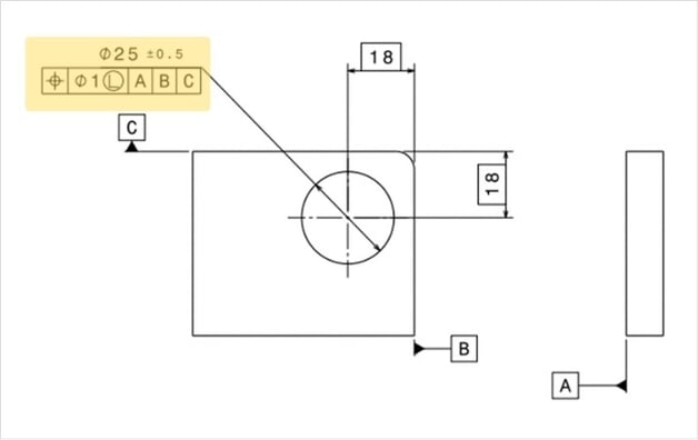
The leftmost segment defines the geometric characteristic—such as position, flatness, or runout—followed by a tolerance value that specifies the allowable variation. Subsequent segments may include material condition modifiers, datum references, or supplementary symbols that refine interpretation.
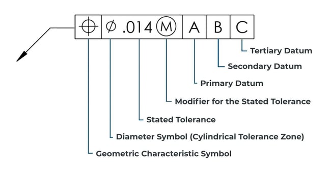
Understanding the reading order is critical.
The geometric characteristic sets the type of tolerance zone, while the tolerance value defines its size.
Material condition modifiers, such as Maximum Material Condition (MMC) or Regardless of Feature Size (RFS), alter how that tolerance is applied relative to part geometry.
Datum references establish the coordinate framework against which the tolerance is evaluated.
Multi-segment Feature Control Frames introduce additional nuance. Composite position tolerances, for example, separate pattern control from feature control, enabling designers to manage both global location and local feature relationships. These constructs are particularly valuable in high-density assemblies where pattern integrity is critical.
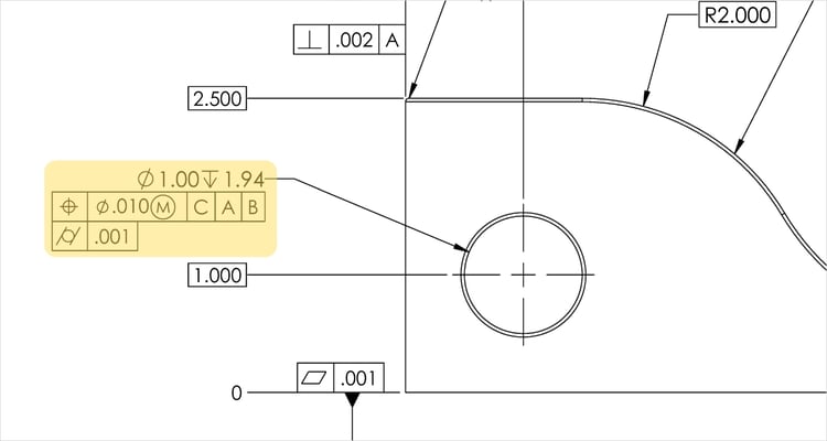
The geometric characteristics defined within Feature Control Frames are typically categorized into five control groups, each governing a different aspect of geometry.
What are form controls?
Form controls regulate the inherent shape of a feature without reference to any external datum.
Straightness, flatness, circularity, and cylindricity are used to ensure that surfaces and features maintain their intended geometry independent of orientation or location.
In precision applications, form tolerances are often applied to sealing surfaces, optical interfaces, or bearing journals, where deviations can lead to leakage, misalignment, or premature wear.
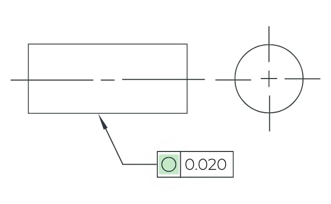
Circularity
A 2D tolerance zone defined by two concentric circles at any given cross‑section
Controls roundness only; does not control axis location or orientation
Applies to circular features such as cylinders, cones, or spheres
Does not require a datum reference; evaluated independently at each cross‑section
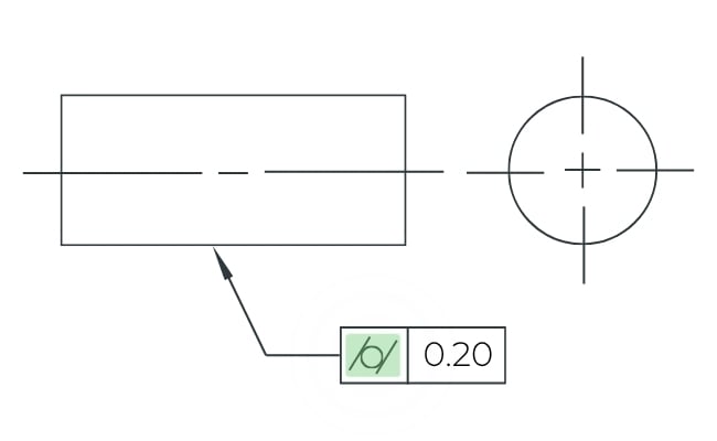
Cylindricity
A 3D tolerance zone bounded by two coaxial cylinders (more restrictive than circularity alone)
Simultaneously controls circularity, straightness, and taper of a cylindrical surface
Applies to cylindrical features only
Does not require a datum reference
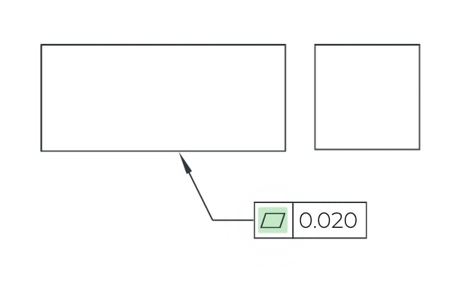
Flatness
A 3D tolerance zone defined by two parallel planes
Controls surface flatness only; does not control orientation or location
Applies to planar surfaces
Does not require a datum reference
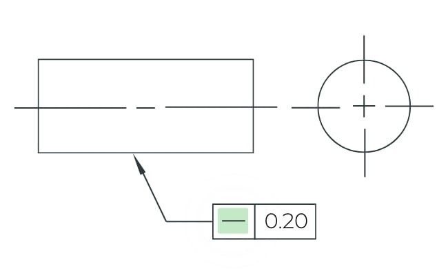
Straightness
A 2D or 3D tolerance zone defined by two parallel lines (for surface elements) or a cylindrical zone (for an axis)
Controls element straightness only; does not control orientation or location
Applies to individual line elements of a surface or to the derived median line (axis) of a feature of size
Does not require a datum reference
What are orientation controls?
Orientation controls define how a feature is angled relative to a datum.
Parallelism, perpendicularity, and angularity are essential for ensuring alignment between components.
In aerospace assemblies, for instance, misalignment introduced by poor perpendicularity control can result in uneven load distribution and accelerated fatigue. Orientation becomes even more critical when components undergo thermal expansion, as differential movement can amplify small angular deviations.
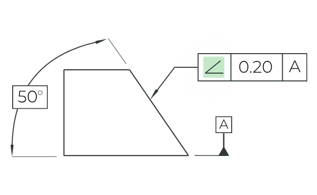
Angularity
A 3D tolerance zone defined by two parallel planes or a cylindrical zone oriented at a specified angle relative to a datum reference frame
Controls the angular orientation of a feature relative to a datum
May be applied to planar surfaces or features of size and used with MMC or LMC
Requires a datum reference
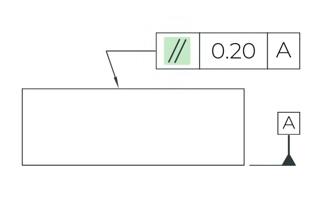
Parallelism
A tolerance zone defined by two parallel planes or a cylindrical zone oriented parallel to a datum
Controls feature orientation relative to a datum
May be applied to surfaces or features of size and used with MMC or LMC
Requires a datum reference
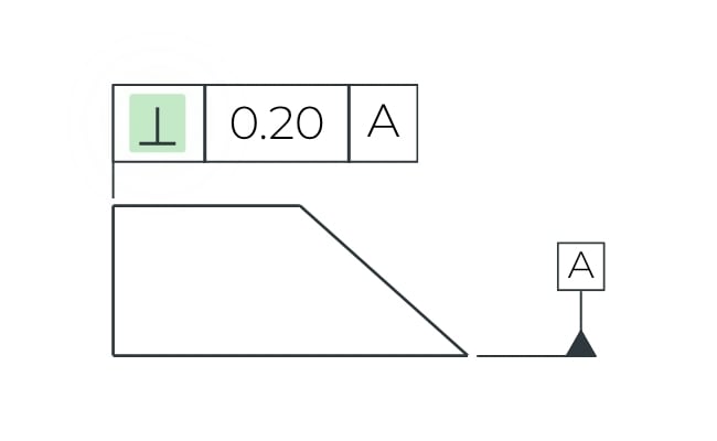
Perpendicularity
A tolerance zone defined by two parallel planes or a cylindrical zone oriented at 90° to a datum
Controls perpendicular orientation relative to a datum
May be applied to surfaces or features of size and used with MMC or LMC
Requires a datum reference
What are location controls?
Location controls, particularly position, govern where features are situated relative to a datum reference frame.
True position is among the most widely used and misunderstood controls, defining a tolerance zone—often cylindrical—within which a feature’s axis or center must reside.
In high-precision assemblies, true position directly affects interchangeability and fit. While concentricity and symmetry exist within this category, their practical application is increasingly limited due to inspection complexity and ambiguity.
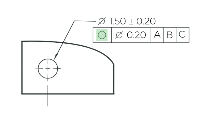
Position
A 3D tolerance zone that surrounds the true position, specified by referencing datum features within the FCF
Used for related features only
May be applied to any feature of size (e.g., hole, slot, boss, tab, or sphere)
Can be used with MMC, LMC, projected tolerances, and tangent planes
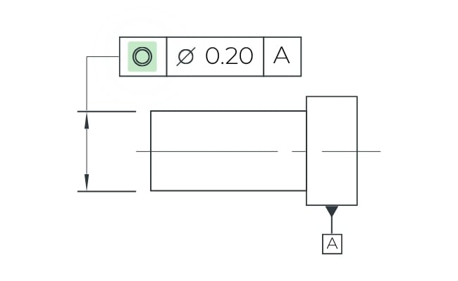
Concentricity
A 3D cylindrical tolerance zone centered about a datum axis, used to control the median points of diametrically opposed elements
Used for related features only
May be applied to features of size that establish an axis (e.g., cylinders, holes, or shafts
Typically replaced by Position or Runout due to complex inspection requirements
Requires a datum reference within the FCF
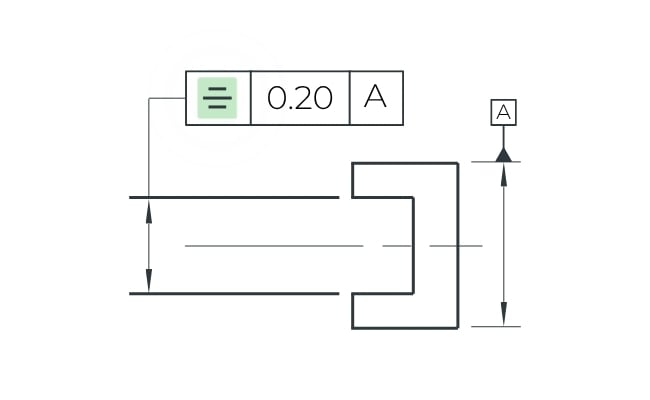
Symmetry
A 3D tolerance zone centered about a datum center plane, used to control median points of a feature
Used for related features only. May be applied to features of size that establish a center plane (e.g., slot, tab, or opposed surfaces)
Typically replaced by Profile or Position
Requires a datum reference within the FCF
What are profile controls?
Profile tolerances provide a versatile means of controlling complex geometries.
Profile tolerances can simultaneously control form, orientation, and location, making them particularly powerful—but also susceptible to overuse.
Profile of a line addresses 2D cross-sections, while profile of a surface governs entire 3D surfaces.
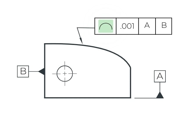
Line Profile
A 2D tolerance zone defined by two equidistant curves about the true profile
Controls form, orientation, and location of a line element
May be applied to any line element of a feature; often used for complex or contoured features
May require datum references depending on function
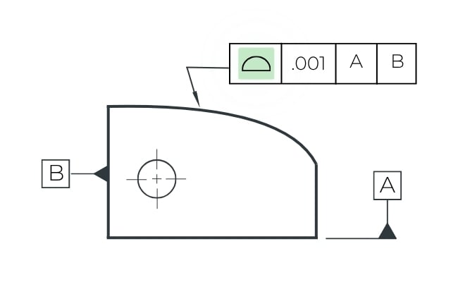
Surface Profile
A 3D tolerance zone defined by two equidistant surfaces about the true profile
Controls form, orientation, and location simultaneously
Applies to complex or free‑form surfaces; can replace multiple individual tolerances
May require datum references
What are runout controls?
Runout controls are specific to rotating components. Circular runout assesses variation in a single cross-section during rotation, while total runout evaluates the entire surface.
These controls are critical for shafts, spindles, and rotating assemblies where dynamic balance and vibration must be managed. In semiconductor equipment, even minimal runout can induce process instability, reinforcing the need for precise rotational control.
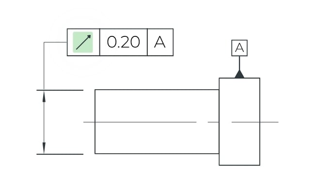
Circular Runout
A 2D tolerance zone evaluated at individual circular elements during rotation about a datum axis
Controls circular form and coaxiality simultaneously at each cross‑section
Applies to surfaces of revolution only; evaluated using a rotating inspection method
Requires a datum axis
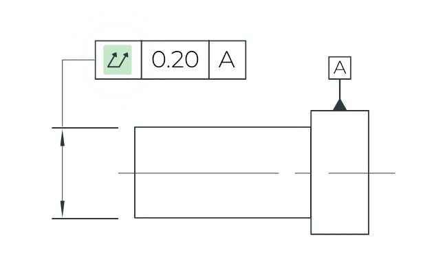
Total Runout
A 3D tolerance zone evaluated across the full length of a surface during rotation
Controls form, orientation, and coaxiality simultaneously
Applies to surfaces of revolution only; more restrictive than circular runout
Requires a datum axis
Feature Control Frame Takeaways for Engineers
FCFs are foundational to precision engineering, providing a structured method for communicating geometric requirements across disciplines. Their effective application requires not only technical understanding but also an appreciation of manufacturing processes, inspection capabilities, and functional performance.
Despite their structured nature, Feature Control Frames are frequently misapplied. Over-constraining geometry can lead to unnecessary manufacturing costs, while under-defining features introduces ambiguity that manifests during inspection.
Clear communication with suppliers is critical to ensure that tolerance requirements are understood and achievable, and effectively using FCFs is a big part of that. Aligning design intent with manufacturing capability reduces the likelihood of non-conformances and rework.
Ultimately, successful application of FCFs requires alignment between design, manufacturing, and quality disciplines. Early collaboration enables more efficient tolerance allocation and ensures that inspection methods are aligned with design intent.
For further reference, engineers are encouraged to consult the latest revisions of ASME Y14.5 and ISO 1101, alongside industry-specific guidance documents. Advanced training in GD&T, coupled with practical experience in metrology and manufacturing, remains essential for mastering the application of Feature Control Frames.