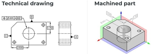
What is a Datum?
A datum is a theoretically exact point, line, axis, plane, or combination thereof derived from the theoretical datum feature simulator.
Updated: 8/19/26
How do datums work?
On any given part, there are three datums (A, B, and C) that are aligned with the primary, secondary, and tertiary planes of a datum reference frame (more on that later).
Datums are determined by selecting specific features on the part. While these features are based on datum planes, they do not always have to be planes themselves.
Datum features are based on points of contact and are ordered according to the degrees of freedom that physically constrain the part (critical for inspection purposes). This is commonly referred to as the 3-2-1 rule, which defines the number of points of contact required to establish the primary, secondary, and tertiary datum planes.
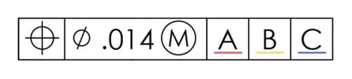
Datum A
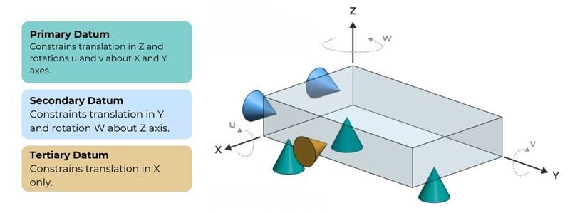
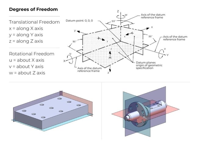
This is the primary datum, as it corresponds to the primary plane. Datum A is the first to make contact and requires at least three points of contact. In the example below, Datum A constrains the Z axis, or translation, and the U and V rotations along the X and Y axes, respectively.
Datum B
Think of this as the secondary datum, which corresponds to the secondary plane. Datum B requires two points of contact and constrains the Y axis and the W rotation along the Z axis.
Datum C
This functions as the tertiary datum and corresponds to the tertiary plane. Datum C is the least important, although not irrelevant, of the datums and has only one point of contact. In the example below, it only constrains the X axis.
What is a datum feature?
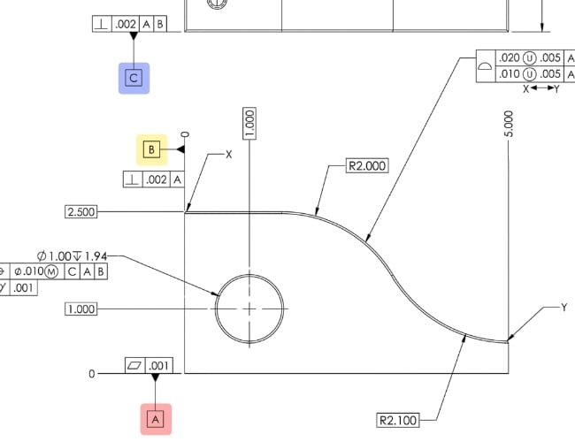
A datum feature is a specific part feature, such as a face or an edge, that's identified with either a datum feature symbol or a datum target signal. These features are associated with real parts and are not theoretical.
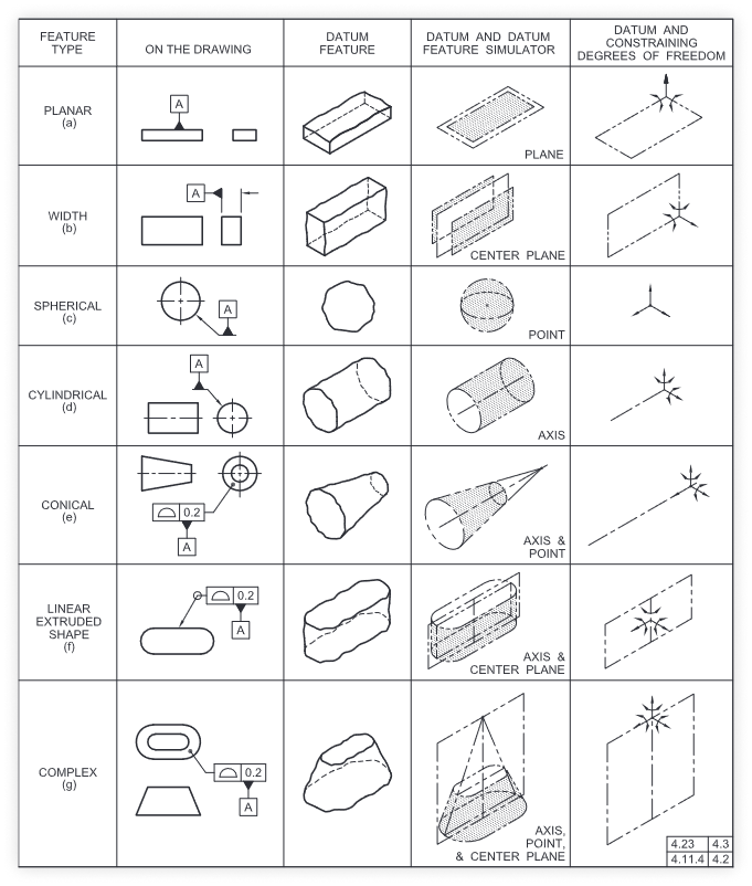
This table lists the different datum features, how they constrain degrees of freedom, and how a datum feature callout is shown on a technical drawing.
What's the difference between a datum and a datum feature?
Before going any further, let's clarify the difference between a datum and a datum feature.
A datum is a theoretically exact point, axis, line, plane, or combination that’s derived from the theoretical datum feature simulator. The most important thing to remember about datums is that they are theoretically exact.
A datum feature is a real part feature (e.g., face, edge, hole, etc.) that’s identified with either a datum feature symbol or a datum target symbol. Datum features are not theoretical.
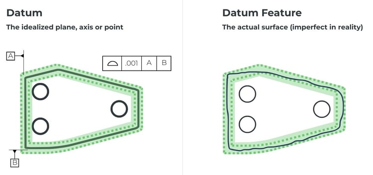
This distinction matters because manufactured parts are inherently imperfect. Datums allow you to compare imperfect reality to a theoretically perfect model, and datums exist within the datum reference frame.
What is a datum reference frame?
A datum reference frame (DRF) is three mutually perpendicular intersecting datum planes that serve as the reference for a component's location, orientation, and form relationships. The datum planes constrain how your part is machined, inspected, and assembled.
The DRF establishes a set of orthogonal planes that are used by all subsequent feature controls and tolerances specified on a part. It provides a common reference point for all dimensions and tolerances, ensuring consistent interpretation and application of GD&T symbols and tolerances.
Your DRF and datums define the degrees of freedom and constrain the part, and the sequence of datum features you choose directly relates the part to the DRF. This is commonly referred to as the 3-2-1 rule, which defines the number of points of contact required to establish the primary, secondary, and tertiary datum planes. These planes constrain the degrees of freedom in translation (x, y, and z axes) and rotation (u, v, and w rotations).
| Datum Level | Typical Constraint | DOF Constrained |
| Primary (A) | 3-point contact surface | 3 DOF |
| Secondary (B) | Edge or face | +2 DOF |
| Tertiary (C) | Perpendicular face/feature | +1 DOF |
A properly constructed DRF must contain these degrees of freedom in a defined sequence:
Datum A
Datum A is the first to make contact and requires at least three points of contact. In the example below, Datum A constrains the Z axis, or translation, and the U and V rotations along the X and Y axes, respectively.
Datum B
Think of this as the secondary datum, which corresponds to the secondary plane. Datum B requires two points of contact and constrains the Y axis and the W rotation along the Z axis.
Datum C
This functions as the tertiary datum and corresponds to the tertiary plane. Datum C is the least important, although not irrelevant, of the datums and has only one point of contact. In the example below, it only constrains the X axis.
How to choose datums?
The most practical thing to know about datums is that they must reflect function—not convenience. Before discussing datum selection strategy, let's walk through the types of datums that are at an engineer's disposal.
What are the types of datums?
Planar Datums
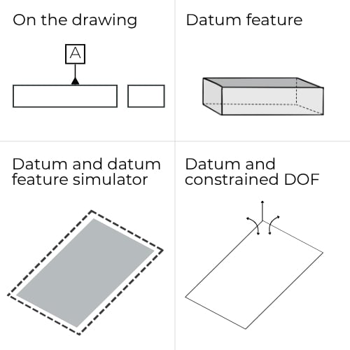
Typically form the primary datum, establish 3 DOF (2 rotations + 1 translation)
- Derived from flat surfaces (e.g., machined faces, mounting pads)
- Used for primary, secondary, or tertiary datums
- Provide the most stability and repeatability in inspection
Example: base plate surface = Datum A (primary plane)
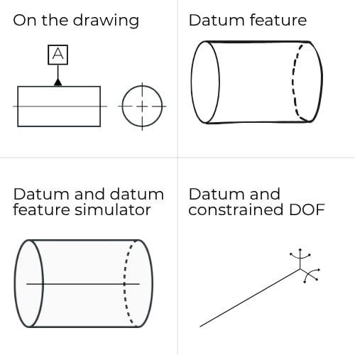
Axial Datums
Often used as secondary or tertiary datums; controls radial positioning and orientation
- Derived from cylindrical features (e.g., holes, pins, and shafts)
- Creates a datum axis
Example: hole pattern centerline = Datum B (axis)
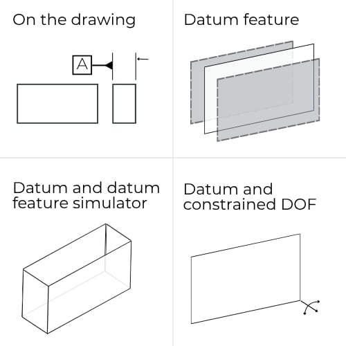
Center/Median Plane Datums
The datum is a plane, but it's derived from a size feature (i.e., not a single surface)
- Derived from features of size with two parallel surfaces
- Represent midpoints between opposing faces
- Provide the most stability and repeatability in inspection
Example: slot or width feature establishes a medium plane datum
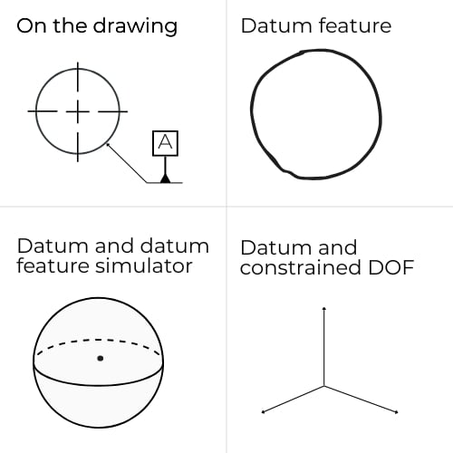
Point and Line Datums
Used for specialized applications, such as datum targets, complex fixturing, and aerospace/freeform geometries
- Rare as primary datums due to limited stability
- More often used as datum targets or constraints rather than full DRF builders
Example: specifying datum targets A1, A2, and A3 on a bracket with a rough casting surface
How to choose the right datum?
A well-selected datum mirrors how the part interfaces in the final assembly, represents critical functional surfaces, and provides stable, repeatable inspection setups, and a well-designed DRF replicates how the part behaves in the assembly.
For example:
- A mounting plate → primary datum = mounting surface
- A shaft → primary datum = axis of rotation
- A housing → primary datum = interface face
This alignment ensures that tolerances directly control functionality, inspection replicates real-world use, and suppliers don’t “pass bad parts” that fail in assembly.
A well-chosen datum solves three persistent engineering problems:
- Ambiguity in drawings – GD&T and datums provide a common language across design, machining, and quality teams
- Inconsistent inspection results – the DRF defines exactly how to orient and measure the part, eliminating interpretation
- Assembly failures – datums tie tolerancing to function, ensuring the part fits, aligns, and performs under load